EasyManuals Logo

Omron CP1E Series User Manual

Omron CP1E Series
260 pages
To Next Page IconTo Next Page
To Previous Page IconTo Previous Page
Page #232 background imageLoading...
Page #232 background image
Appendices
A-16
CP1E CPU Unit Hardware User’s Manual(W479)
The first input word allocated to the Expansion I/O Unit is CIO m and the first output word is CIO n.
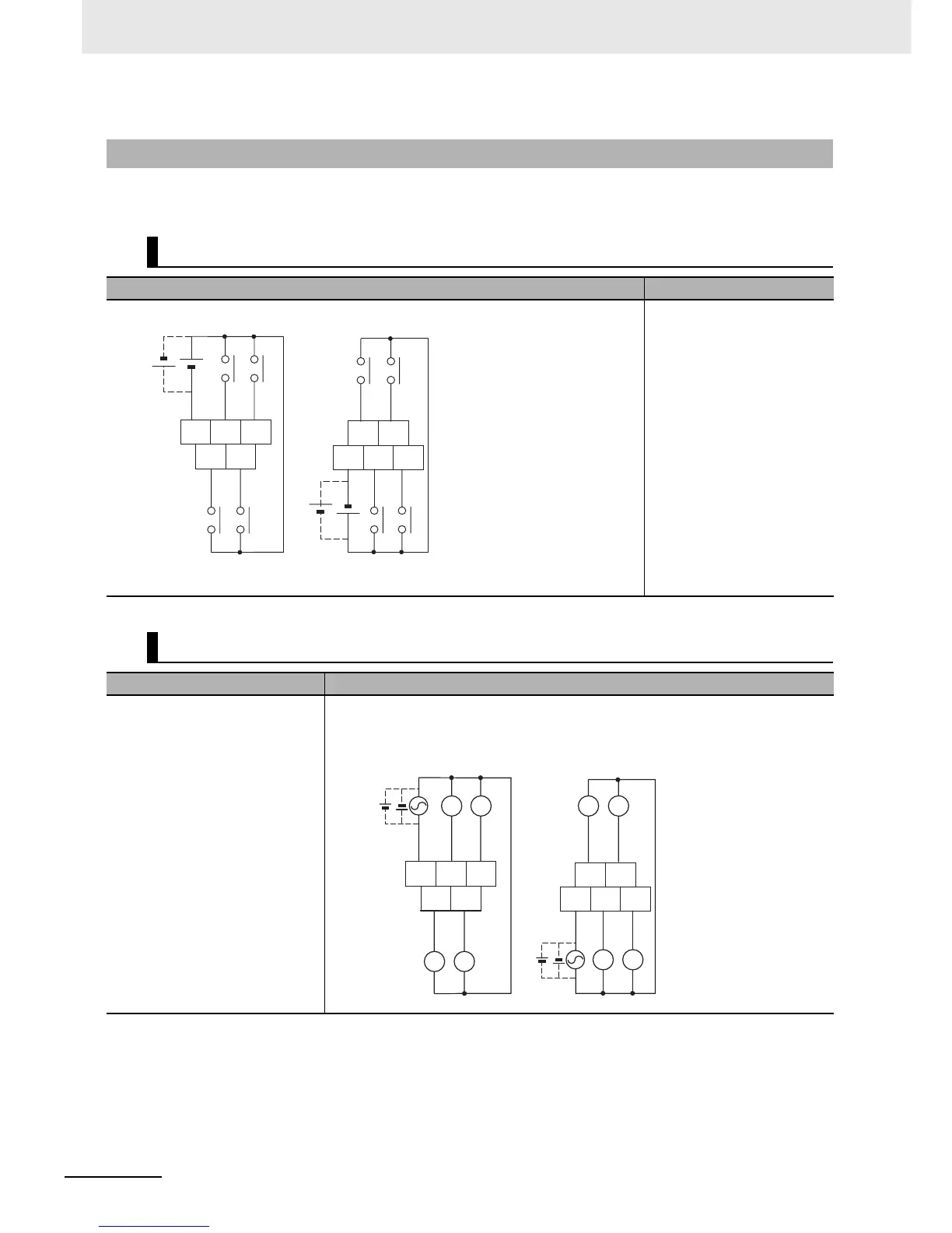
A-3-2 Expansion I/O Units
8-point Input Unit
Input Wiring Diagram Output Wiring Diagram
Outputs not provided.
8-point Output Units
Input Wiring Diagram Output Wiring Diagram
Inputs not provided.
z Relay Outputs
CP1W-8ER
24V DC
24V DC
-
+
+
-
-
+
+
-
CIO m
COM 01 03
00 02
COM 05 07
04 06
The COM terminals
on the upper terminal
block and the COM
terminals on the lower
terminal block are
internally connected,
but they must also be
wired externally.
Unit Upper Terminal Block Unit Lower Terminal Block
L L
L L
L L
L L
CIO n
Unit Lower Terminal Block
24V DC
24V DC
Unit Upper Terminal Block
COM 01 03
00 02
COM 05 07
04 06

Table of Contents

Questions and Answers:

Question and Answer IconNeed help?

Do you have a question about the Omron CP1E Series and is the answer not in the manual?

Omron CP1E Series Specifications

General IconGeneral
Data Memory8K words
Pulse Output100 kHz for 2 axes
Communication PortsRS-232C, USB
MountingDIN rail mounting
Analog InputsOptional (via expansion units)
Analog OutputsOptional (via expansion units)
Expansion UnitsDigital I/O, Analog I/O, Temperature Sensor Units
Power Supply100 to 240 VAC or 24 VDC
CPU TypeVarious (E, N, and NA types)

Related product manuals