9-27
9 Using Expansion Units and Expansion I/O Units
CP1E CPU Unit Hardware User’s Manual(W479)
9-3 Analog I/O Units
9
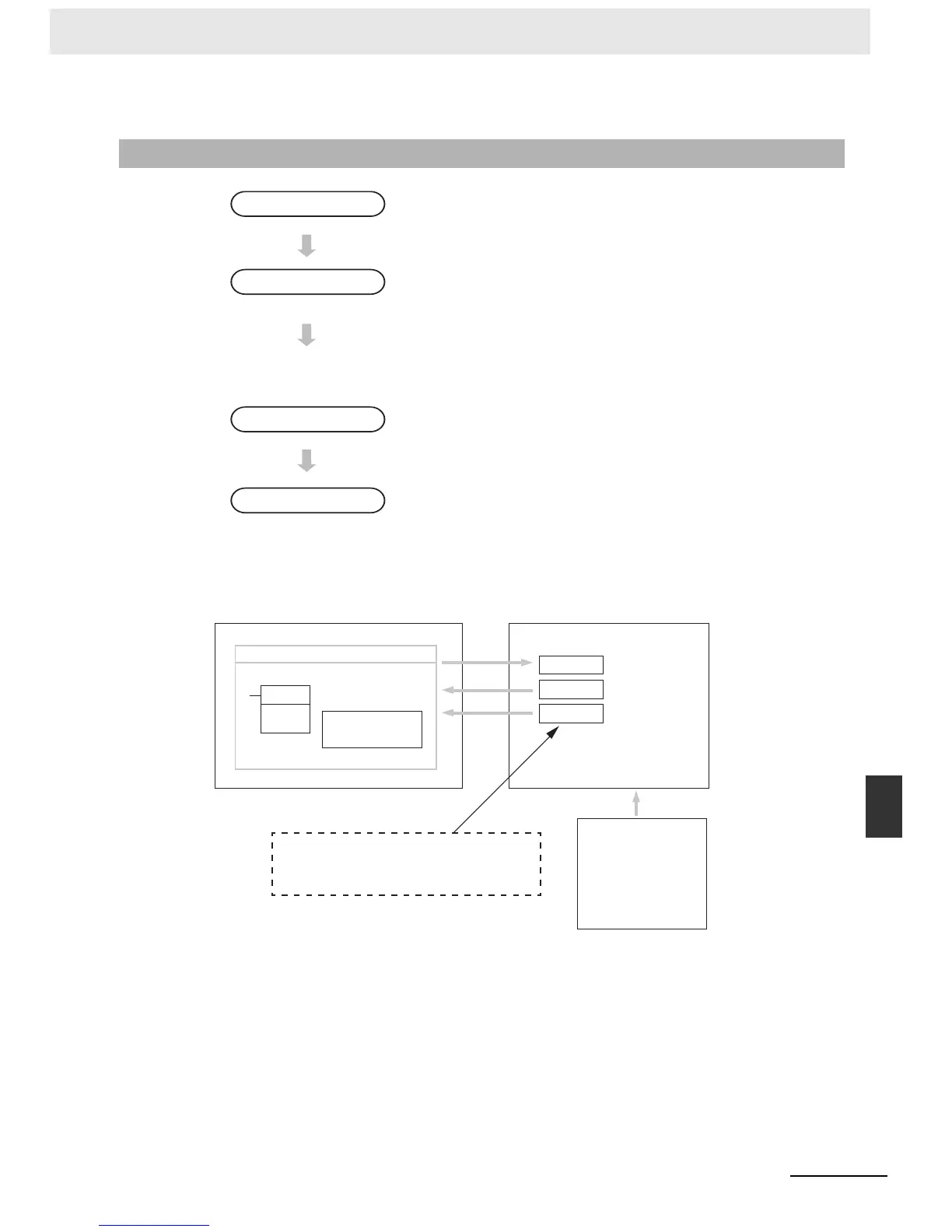
9-3-4 Flow of Processing
z Reading Range Code Settings and A/D Conversion Data
9-3-4 Flow of Processing
1
• Connect the Analog I/O Unit.
2
• Set the I/O ranges.
• Analog inputs: 0 to 5 VDC, 1 to 5 VDC, 0 to 10 VDC, –10 to 10
VDC, 0 to 20 mA, or 4 to 20 mA
• Analog output: 1 to 5 VDC, 0 to 10 VDC, –10 to 10 VDC, 0 to 20
mA, or 4 to 20 mA
• Set analog inputs as voltage or current inputs and set the averag-
ing function.
3
• Connect analog I/O devices.
4
• Write the range code.
• Analog inputs: Read converted data.
• Analog output: Write set values.
Connect the Unit.
Set the I/O ranges.
Wire the analog I/O.
Program operation in
the ladder program.
MOV(21)
MOVE instruction
Ladder program
Range code
Word n + 1
Word m + 1
Word m + 2
CPU Unit Analog I/O Unit
• Writes the range code.
• Reads the converted
values.
Analog input 0
converted value
Analog input 1
converted value
“m
”
is the last input word and
“
n
”
is the last
output word allocated to the CPU Unit or
previous Expansion Unit or Expansion I/O Unit.
Analog I/O devices
• Temperature sensor
• Pressure sensor
• Speed sensor
• Flow sensor
• Voltage/current meter
• Other

 Loading...


