5-13
5 Installation and Wiring
CP1E CPU Unit Hardware User’s Manual(W479)
5-2 Installation
5
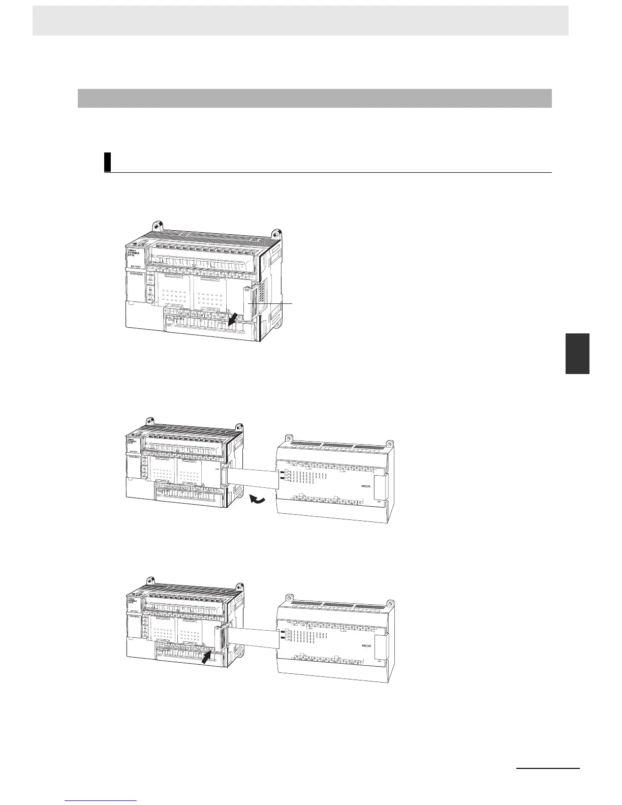
5-2-4 Connecting Expansion I/O Units and Expansion Units
This section describes how to connect Expansion I/O Units and Expansion Units.
1
Remove the cover from the CPU Unit’s or the Expansion I/O Unit’s expansion connector. Use a
flat-head screwdriver to remove the cover from the Expansion I/O Connector.
2
Insert the Expansion I/O Unit’s connecting cable into the CPU Unit’s or the Expansion I/O Unit’s
expansion connector.
3
Attach the cover to the CPU Unit’s or the Expansion I/O Unit’s expansion connector.
5-2-4 Connecting Expansion I/O Units and Expansion Units
Connection Methods
Remove
Expansion Connector
Cover
IN
OUT
Insert
Attach
IN
OUT

 Loading...


