EasyManuals Logo

Omron CP1E Series User Manual

Omron CP1E Series
260 pages
To Next Page IconTo Next Page
To Previous Page IconTo Previous Page
Page #118 background imageLoading...
Page #118 background image
5 Installation and Wiring
5-12
CP1E CPU Unit Hardware User’s Manual(W479)
Precautions for Correct UsePrecautions for Correct Use
Tighten terminal block screws and cable screws to the following torques.
M4: 1.2 N·m
M3: 0.5 N·m
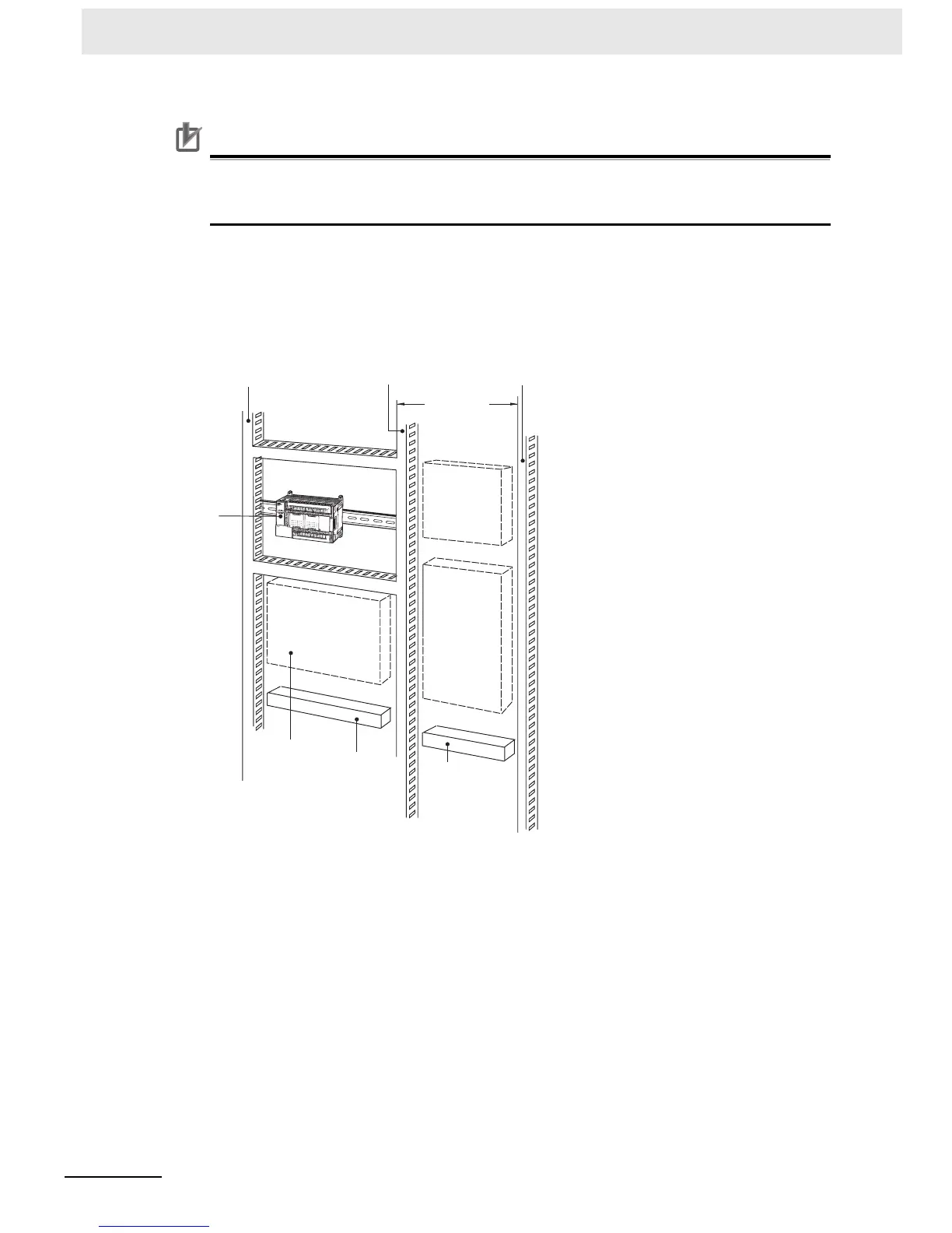
z Routing Wiring Ducts
Install the wiring ducts at least 20 mm between the tops of the Racks and any other objects, (e.g.,
ceiling, wiring ducts, structural supports, devices, etc.) to provide enough space for air circulation
and replacement of Units.
Input duct Output duct Power duct
200 mm min.
CP1E
Breaker
Fuse
Power
equipment,
such as
transformers
and magnetic
relays
Terminal blocks
for power
equipment
Terminal
blocks for
PLC
Fuses, timers,
relays, etc.
(Not heat-
generating
equipment or
power
equipment.)

Table of Contents

Questions and Answers:

Question and Answer IconNeed help?

Do you have a question about the Omron CP1E Series and is the answer not in the manual?

Omron CP1E Series Specifications

General IconGeneral
Data Memory8K words
Pulse Output100 kHz for 2 axes
Communication PortsRS-232C, USB
MountingDIN rail mounting
Analog InputsOptional (via expansion units)
Analog OutputsOptional (via expansion units)
Expansion UnitsDigital I/O, Analog I/O, Temperature Sensor Units
Power Supply100 to 240 VAC or 24 VDC
CPU TypeVarious (E, N, and NA types)

Related product manuals