5-11
5 Installation and Wiring
CP1E CPU Unit Hardware User’s Manual(W479)
5-2 Installation
5
5-2-3 Installation
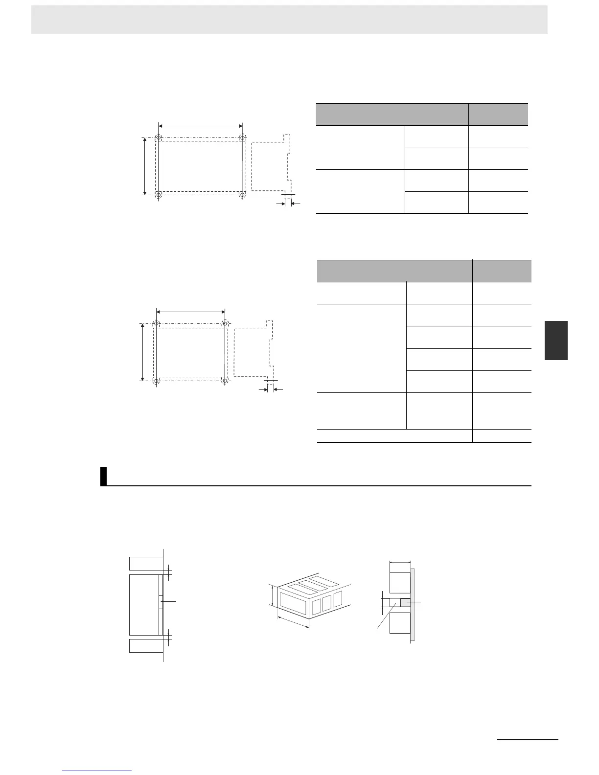
z Surface Installation Mounting Hole Pitch
• CP1E CPU Units with 30 or 40 I/O Points or Expansion I/O Units with 32 or 40 I/O Points
• CP1E CPU Units with 20 I/O Points, Expansion I/O Units with 8, 16, or 20 I/O Points, and Expan-
sion Units
Whenever possible, route I/O wiring through wiring ducts. Install the ducts so that it is easy to wire the
I/O Units through the ducts. It is handy to have the ducts at the same height as the Racks. Use mount-
ing bases if necessary to adjust the heights.
Unit
Mounting hole
pitch A (mm)
CP1E CPU Unit Unit with 30 I/O
points
120±0.5
Unit with 40 I/O
points
140±0.5
Expansion I/O Units Unit with 32 I/O
points
140±0.2
Unit with 40 I/O
points
140±0.2
Unit
Mounting hole
pitch A (mm)
CP1E CPU Unit Unit with 20 I/O
points
76±0.5
Expansion I/O Units Unit with 8 input
points
56±0.2
Unit with 8 output
points
56±0.2
Unit with 16 out-
put points
76±0.2
Unit with 20 I/O
points
76±0.2
Analog I/O Units Analog I/O
Analog input
Analog output
76±0.2
Temperature Sensor Units 76±0.2
Using Wiring Ducts
100mm
8mm
A
CP1E CPU Unit with 30 or
40 I/O Points
Expansion I/O Unit with
32 or 40 I/O Points
8mm
100mm
A
CP1E CPU Unit with
20 I/O Points
Expansion I/O Unit
with 8, 16, or 20 I/O
Points
Expansion Unit
40mm
30mm
30mm
81.6~89.0mm
CPU
Rack
Mounting bracket
Duct
Duct
Duct
Unit
20mm min.
20mm min.
DIN Track

 Loading...


