5 Installation and Wiring
5-10
CP1E CPU Unit Hardware User’s Manual(W479)
3
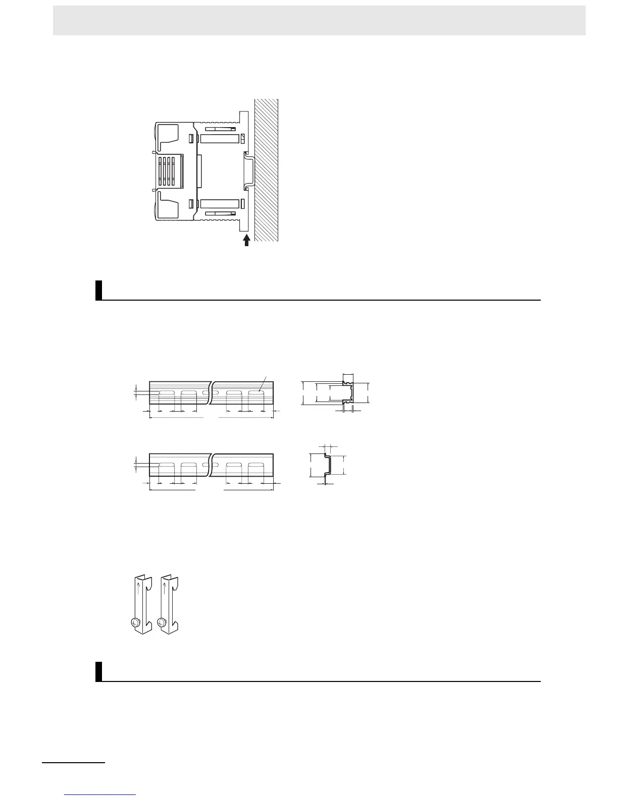
Press in all of the DIN Track mounting pins to securely lock the Units in place.
z DIN Track
Secure the DIN Track to the control panel using M4 screws at interval of 210 mm or less (6 holes or
fewer). The tightening torque is 1.2 N·m.
z End Plate
Use the PFP-M End Plates to secure the Units so that they do not move towards one end or the
other of the DIN Track.
z Surface Installation
• Create the mounting holes in the mounting surface as shown in the dimensions diagrams.
• Align the CP1E CPU Unit with the mounting holes and secure it in place with M4 screws.
Mounting Brackets
Surface Installation
DIN Track mounting pins
15
10
4.5
25
25
25
10
25
15
1000
1000(500)*
PFP-100N2
PFP-100N/50N
15
10
4.5
25 25
25
10
25 15(5)*
1
16
1.51
29.2
zz
27
28-25 × 4.5 long holes
30±0.3
7.3±0.15
35±0.3 27±0.15
*PFP-50N dimensions are given in parentheses.

 Loading...


