9 Using Expansion Units and Expansion I/O Units
9-50
CP1E CPU Unit Hardware User’s Manual(W479)
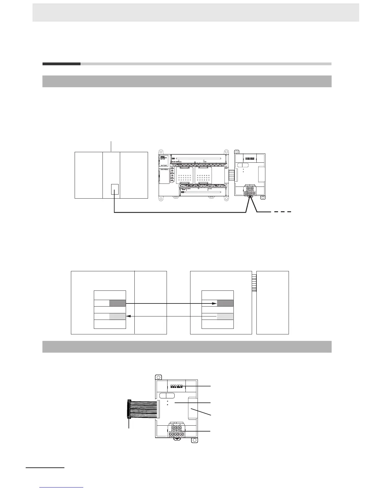
9-5 CompoBus/S I/O Link Units
The CP1E CPU Unit can function as a slave to a CompoBus/S Master Unit when a CP1W-SRT21 Com-
poBus/S I/O Link Unit is connected. The CompoBus/S I/O Link Unit establishes an I/O link of 8 inputs
and 8 outputs between the Master Unit and the PLC.
From the standpoint of the CP1E CPU Unit, the 8 input bits and 8 output bits allocated to the Compo-
Bus/S I/O Link Unit are identical to input and output bits allocated to Expansion I/O Units even though
the CompoBus/S I/O Link Unit does not control actual inputs and outputs, i.e., I/O is performed for I/O
memory in the CPU Unit to which the CompoBus/S Master Unit is mounted.
z CP1W-SRT21 CompoBus/S I/O Link Unit
9-5-1 Overview
9-5-2 Part Names and Functions
B D L NC( B S - ) N C
B D H NC( B S +
)
S
COMM
ERR
ON
12 3
4
5
6
No.
SRT21
EXP
Special flat cable or VCTF cable
CompoBus/S Master Unit
(or SRM1 CompoBus/S
Master Control Unit)
CP1W-SRT21
CompoBus/S
I/O Link Unit
CP1E CPU Unit
Master PLC (CS Series)
CPU Unit
CP1E (CPU Unit with 30 or 40 I/O Points)
I/O memory
Input
CIO 2
Output
CIO 102
8 bits
8 bits
I/O memory
Input
CIO 2004
Output
CIO 2000
8 bits
8 bits
CompoBus/S
Master Unit
Unit No. 0
CompoBus/S
I/O Link Unit
Node
number: 0
BD NC(BS- ) NC
BD NC(BS+ )
S
COMM
ERR
ON
132
4
5
6
No.
SRT21
EXP
(1) CompoBus/S Terminals
(3) LED Indicators
(4) Expansion I/O Connecting Cable
(5) Expansion Connector
(2) DIP Switch

 Loading...


