9-51
9 Using Expansion Units and Expansion I/O Units
CP1E CPU Unit Hardware User’s Manual(W479)
9-5 CompoBus/S I/O Link Units
9
9-5-2 Part Names and Functions
(1)CompoBus/S Terminals
The following CompoBus/S terminals are provided: CompoBus/S communications data high/low
terminals, NC terminals for communications power supply plus (+) and minus (-), and an NC ter-
minal. (Power is supplied internally for this Unit, so the NC terminals for communications power
supply can be used as relay terminals.)
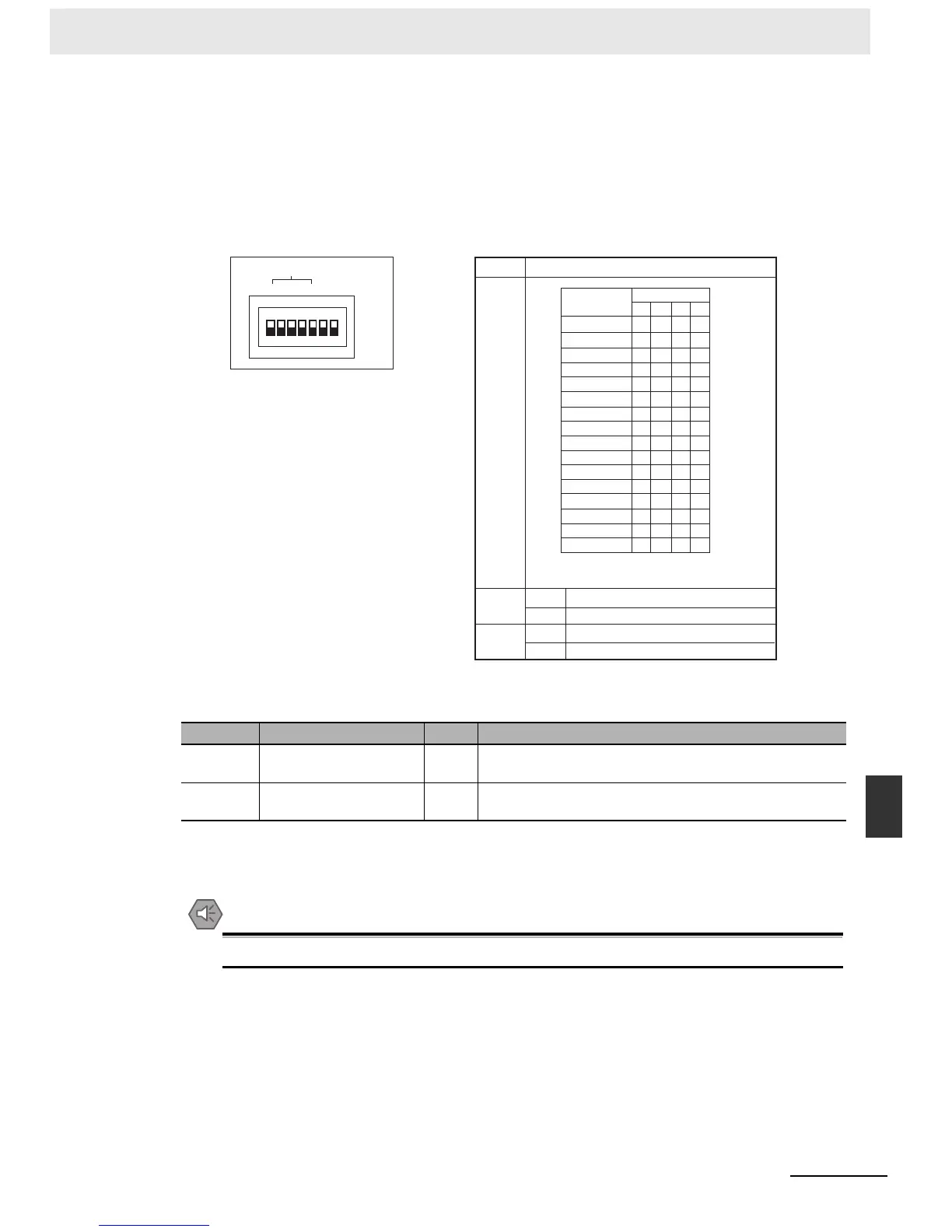
(2)DIP Switch
Used to specify the node number for the CompoBus/S I/O Link Unit.
(3)LED Indicators
Used to show the CompoBus/S communications status.
(4)Expansion I/O Connecting Cable
Connected to the expansion connector of a CP1E CPU Unit or an Expansion Unit or Expansion
I/O Unit. The cable is provided with the CompoBus/S I/O Link Unit and cannot be removed.
Precautions for Safe Use
Do not touch the cables during operation. Static electricity may cause operating errors.
(5)Expansion Connector
Used to connect Expansion Units or Expansion I/O Units.
Indicator Name Color Meaning
COMM Communications indicator Yellow ON: Communications in progress.
OFF: Communications stopped or error has occurred.
ERR Error indicator Red ON: A communications error has occurred.
OFF: Indicates normal communications or stand-by.
Pin labels Contents
1
2
4
8
DR
HOLD
0
1
2
3
4
5
6
7
8
9
10
11
12
13
14
15
1 = ON, 0 = OFF
ON
OFF
ON
OFF
Long-distance communications mode *
High-speed communications mode
Retain inputs after a communications error.
Clear inputs after a communications error.
ON
1
2
4
8
DR
HOLD
SW1
8 4 2 1
0 0 0 0
0 0 0 1
0 0 1 0
0 0 1 1
0 1 0 0
0 1 0 1
0 1 1 0
0 1 1 1
1 0 0 0
1 0 0 1
1 0 1 0
1 0 1 1
1 1 0 0
1 1 0 1
1 1 1 0
1 1 1 1
NODE NUMBER
SW1
Node Number
Setting
* The long-distance communications mode
can be used only when one of the
following Master Units is connected:
C200HW-SRM21-V1, CQM1-SRM21-V1,
or SRM1-C0@-V2.

 Loading...


