A-41
Appendices
CP1E CPU Unit Hardware User’s Manual(W479)
A-4 Wiring for Serial
Communications
App
A-4-4 Reducing Electrical Noise for External Wiring
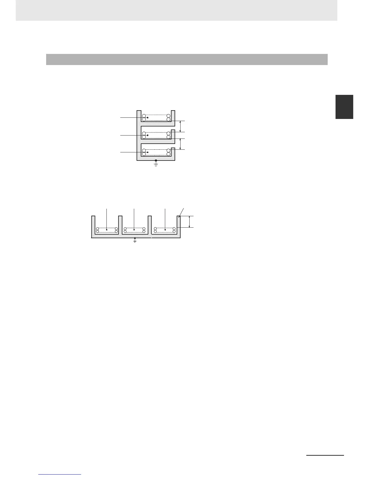
Observe the following precautions when wiring communications cables.
• When multi-conductor signal cable is being used, avoid combining I/O wires and other control wires
in the same cable.
• If wiring racks are parallel, allow at least 300 mm between them.
• If the I/O wiring and power cables must be placed in the same duct, they must be shielded from each
other using grounded steel sheet metal.
A-4-4 Reducing Electrical Noise for External Wiring
Communications
cables
Low-current cables
PLC power supply
and general control
circuit wiring
Power lines
300 mm min.
Ground to 100 Ω or less.
Control cables
Power cables
300 mm min.
Communications
cables
PLC power supply
and general control
circuit wiring
Power lines
200 mm min.
Ground to 100
Ω or less.
Steel sheet metal

 Loading...


