5-7
5 Installation and Wiring
CP1E CPU Unit Hardware User’s Manual(W479)
5-2 Installation
5
5-2-2 Unit Arrangement
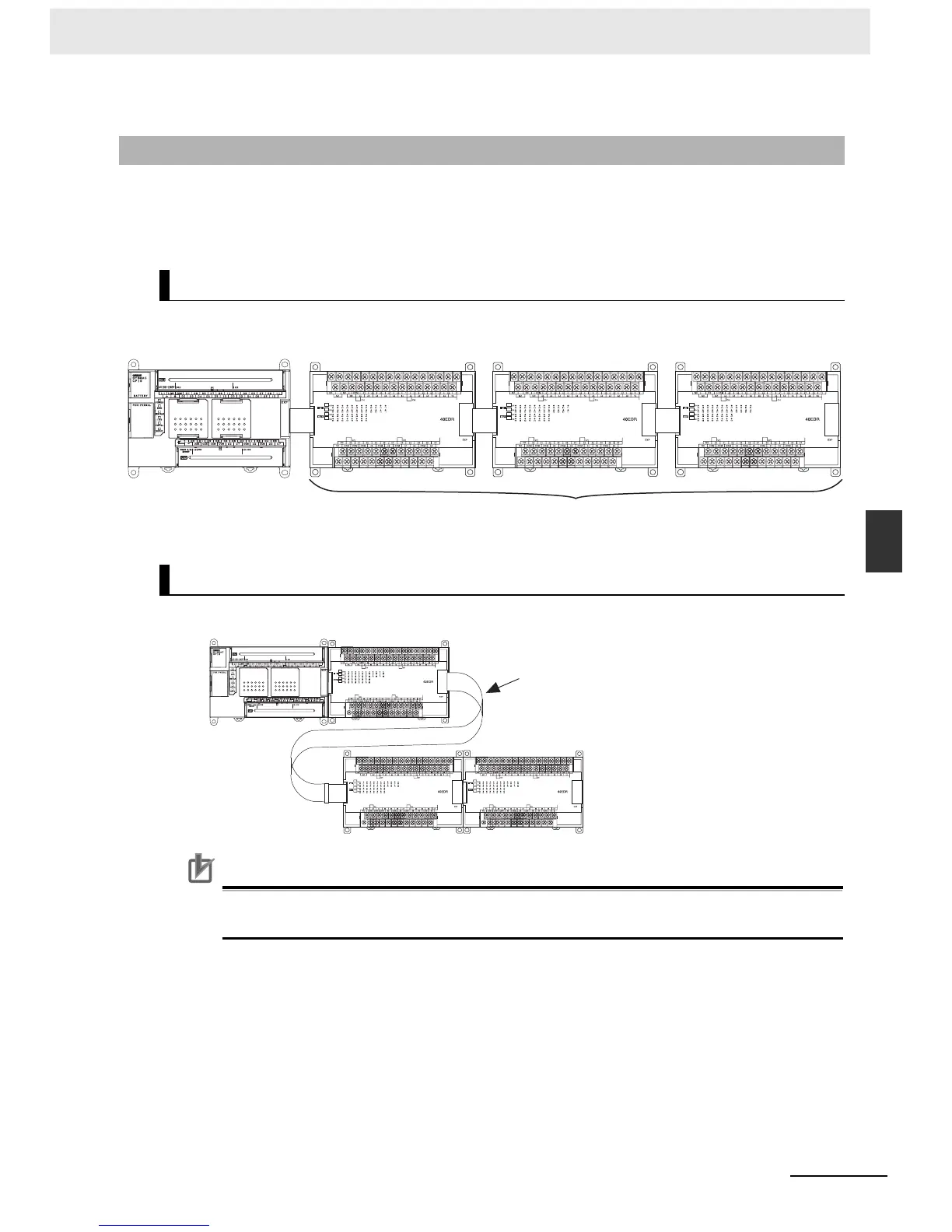
This section describes how to arrange the CP1E Units.
As shown in the following diagrams, Units can be arranged in one or two rows when Expansion I/O
Units or Expansion Units are used.
Expansion I/O Units and Expansion Units can be installed in a side-by-side arrangement.
The Units can be arranged in two rows using the CP1W-CN811 I/O Connecting Cable (800 mm).
Precautions for Correct UsePrecautions for Correct Use
I/O Connecting Cable can be used in one place only in each CP1E PLC. It cannot be used in
more than one place in the same CP1E PLC.
5-2-2 Unit Arrangement
Arrangement in One Row
Arrangement in Two Rows
CP-series Expansion Units and Expansion I/O Units
CP1E CPU Unit
CP1W-CN811 I/O
Connecting Cable

 Loading...


