5 Installation and Wiring
5-8
CP1E CPU Unit Hardware User’s Manual(W479)
This section describes how to install the CP1E.
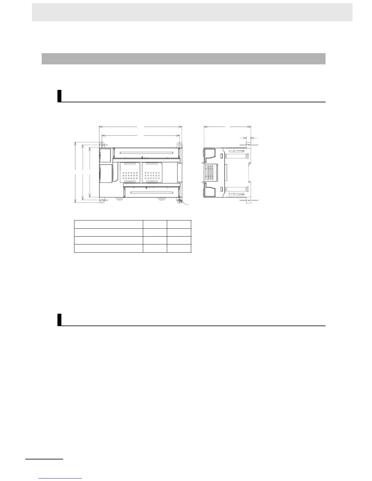
z Dimensions
z Installation Height
The installation height is approximately 90 mm.
When a cable is connected to an Option Board, however, the additional height must be included.
Always allow for the additional height when considering the depth of the control panel in which the
PLC is to be mounted.
There are two installation methods.
z DIN Track Installation
• Units can be mounted to PEP-50N (50 cm) or PEP-100N/100N2 (100 cm) DIN Tracks.
• Units can be moved and removed easily.
• The installation height in the control panel will be increased depending on the type of DIN tracks
used.
z Surface Installation
Units can be directly mounted in the control panel using M4 screws.
5-2-3 Installation
Installation Dimensions and Height
Model number W1 W2
CP1E-20D-A 86 76
CP1E-30D-A 130 120
CP1E-40D-A 150 140
Installation Methods
W1
W2
85
8
110 100 90
4-
φ
4.5

 Loading...


