5 Installation and Wiring
5-18
CP1E CPU Unit Hardware User’s Manual(W479)
Precautions for Correct UsePrecautions for Correct Use
• Loose pieces of wires may fall in the area when wiring. To prevent these pieces from entering
into the Unit, leave the label on the top of the Unit while wiring.
• Remove the label after the completion of wiring to ensure proper heat dissipation.
• The power supply terminals are located at the top of the Unit. Do not connect a power supply
to the 24-VDC external supply terminals on the bottom of the Unit. Internal circuits may be
damaged if power is supplied to these terminals.
Precautions for Safe Use
• Never apply a voltage that exceeds the input voltage for Input Units or the maximum switching
capacity for Output Units.
• When the power supply has positive and negative terminals, always wire them correctly.
• Do not bend the I/O Connecting cable past its natural bending radius or pull in it with excessive
force. Doing so will damage the cable.
z Wire Sizes
• AWG22 to AWG18 (0.32 to 0.82 mm
2
) power lines are recommended.
• The current capacity of electric wire depends on factors such as the ambient temperature and
insulation thickness, as well as the gauge of the wire.
z Crimp Terminals
• M3 self-rising terminal screws are used.
• Use crimp terminals or solid wire for wiring.
• Do not connect bare stranded wires directly to terminals.
• Tighten the terminal block screws to the torque of 0.5 N·m.
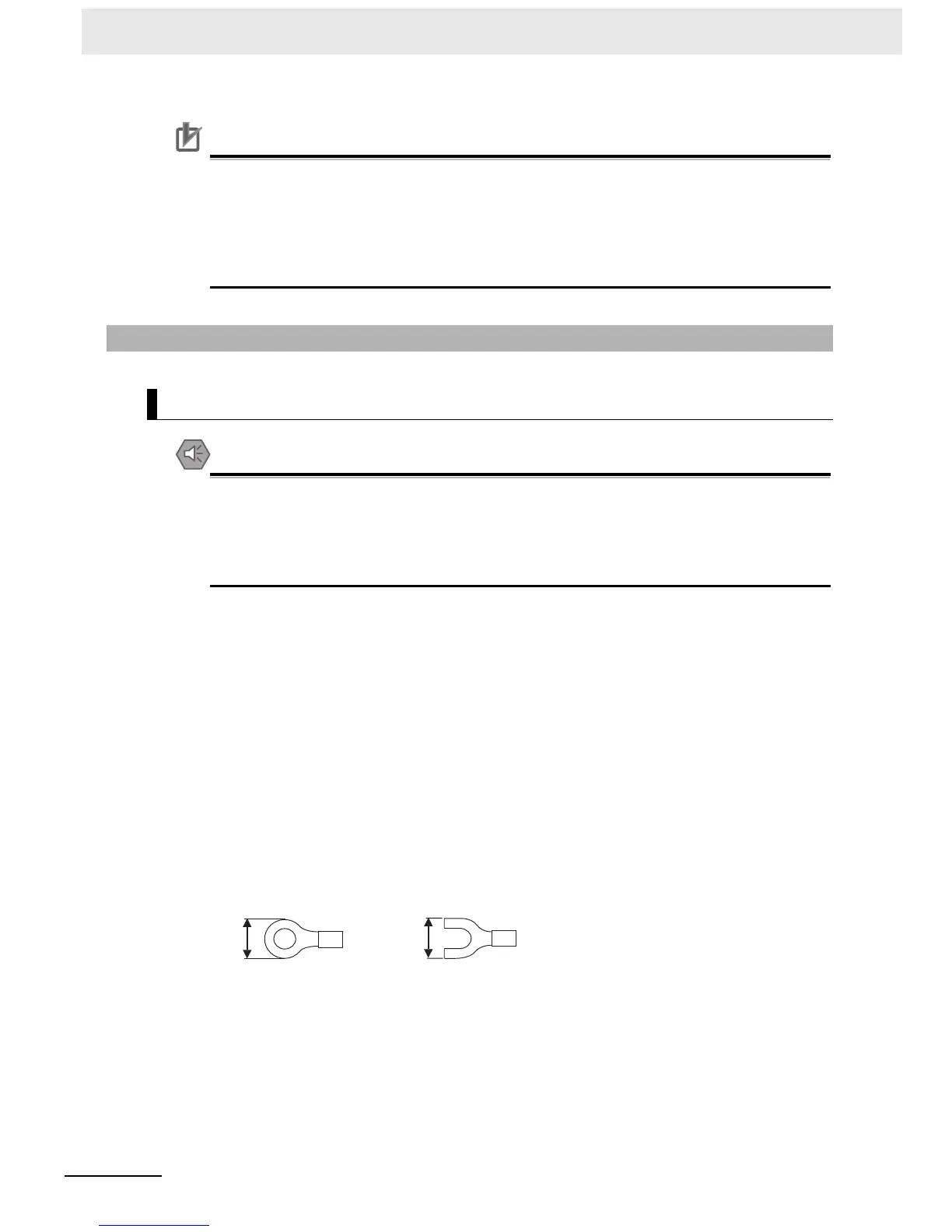
• Use crimp terminals (M3) having the dimensions shown below.
z Wiring
• Wire the Units so that they can be easily replaced.
• Make sure that the I/O indicators are not covered by the wiring.
• Do not place the I/O wiring in the same conduits or ducts as high-voltage or power lines. Inductive
noise can cause errors or damage.
• Tighten the terminal screws to the torque of 0.5 N·m.
5-3-3 I/O Wiring
I/O Wiring
6.2 mm max.
6.2 mm max.

 Loading...


