A-17
Appendices
CP1E CPU Unit Hardware User’s Manual(W479)
A-3 Wiring Diagrams
App
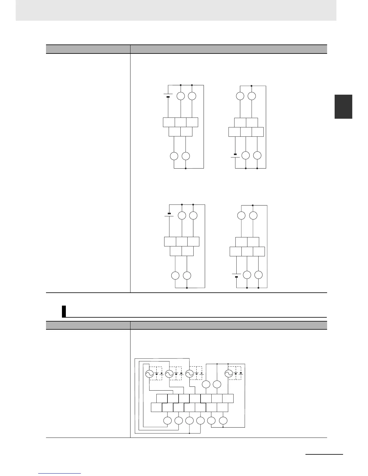
A-3-2 Expansion I/O Units
Inputs not provided.
z Transistor Outputs (Sinking)
CP1W-8ET
z Transistor Outputs (Sourcing)
CP1W-8ET1
16-point Output Units
Input Wiring Diagram Output Wiring Diagram
Inputs not provided.
z Relay Outputs
CP1W-16ER
Input Wiring Diagram Output Wiring Diagram
L L
L L
L L
L L
-
+
-
+
Unit Lower Terminal BlockUnit Upper Terminal Block
COM 05 07
04 06
COM 01 03
00 02
4.5 to 30 VDC
4.5 to 30 VDC
CIO n
L L
L L
L L
L L
-
+
-
+
COM 05 07
04 06
COM 01 03
00 02
4.5 to 30 VDC
4.5 to 30 VDC
CIO n
Unit Lower Terminal BlockUnit Upper Terminal Block
L L LL L L
L L
CIO n
Unit Upper Terminal Block
NC COM COM COM 04 06
COM
NC 00 01 02 03 05
07

 Loading...


