EasyManuals Logo

Omron CP1E Series User Manual

Omron CP1E Series
260 pages
To Next Page IconTo Next Page
To Previous Page IconTo Previous Page
Page #234 background imageLoading...
Page #234 background image
Appendices
A-18
CP1E CPU Unit Hardware User’s Manual(W479)
Inputs not provided.
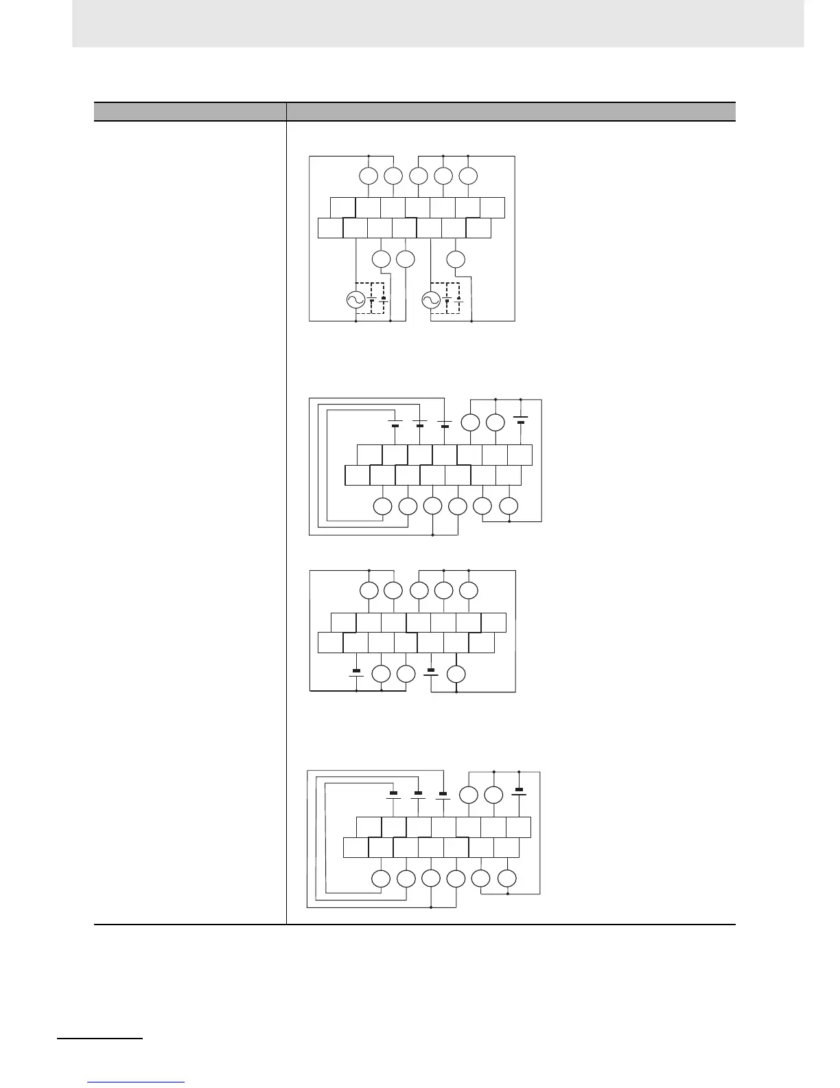
z Transistor Outputs (Sinking)
CP1W-16ET
z Transistor Outputs (Sourcing)
CP1W-16ET1
Input Wiring Diagram Output Wiring Diagram
NC 00 02 04 05 07 NC
NC COM 01 03 COM 06 NC
L L
L
L L L L L
CIO n+1
Unit Lower Terminal Block
L
L
L
NC COM COM COM 04 06 COM
NC 00 01 02 03 05 07
L L
L
L L
NC 00 02 04 05 07 NC
NC COM 01 03 COM 06 NC
L L L
L L L L L
Unit Lower Terminal Block
Unit Upper Terminal Block
CIO n
CIO n+1
L
L
L
NC COM COM COM 04 06 COM
NC 00 01 02 03 05 07
L
L
L
L L
Unit Upper Terminal Block
CIO n

Table of Contents

Questions and Answers:

Question and Answer IconNeed help?

Do you have a question about the Omron CP1E Series and is the answer not in the manual?

Omron CP1E Series Specifications

General IconGeneral
Data Memory8K words
Pulse Output100 kHz for 2 axes
Communication PortsRS-232C, USB
MountingDIN rail mounting
Analog InputsOptional (via expansion units)
Analog OutputsOptional (via expansion units)
Expansion UnitsDigital I/O, Analog I/O, Temperature Sensor Units
Power Supply100 to 240 VAC or 24 VDC
CPU TypeVarious (E, N, and NA types)

Related product manuals