3-13
3 Part Names and Functions
CP1E CPU Unit Hardware User’s Manual(W479)
3-1 CPU Units
3
3-1-3 Common I/O Specifications
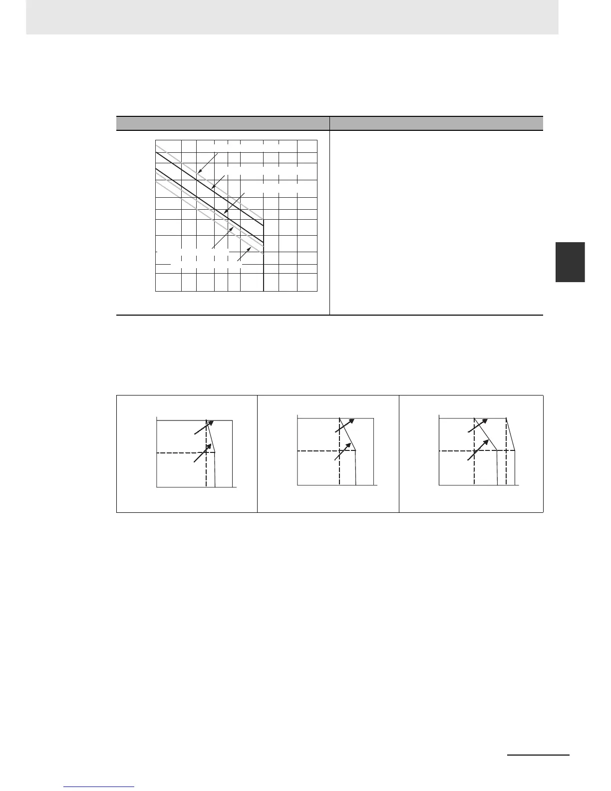
z Estimating the Service Life of Relays
Under normal conditions, the service life of output contacts is as shown above. The service life of
relays is as shown in the following diagram as a guideline.
z Relationship between Continuous Simultaneous ON Rate and Ambient
Temperature
There are restrictions on the power supply voltage and relay output load current imposed by the
ambient temperature. Make sure that the power supply voltage and relay output load current are
within the following ranges.
Note The above restrictions apply to the relay output load current from the CPU Unit even if Expansion I/O Units
are not connected.
CP1E-20DR- CP1E-30/40DR-
CP1E-N20DR-D CP1E-N30DR-D CP1E-N40DR-D
30-VDC/250-VAC resistive load
300
500
200
100
50
30
20
5
3
2
10
0.1
125-VAC resistive load
30 VDC, τ = 7ms
125 VAC cosφ= 0.4
250 VAC cosφ= 0.4
Contact current (A)
Life (x 10
4
)
0.2 0.3 0.5 0.7 1 2 3 5 10
50%
100%
55
˚C
45
0%
Power voltage
DC21.6V
Power voltage
DC20.4V
Ambient temperature
40
50%
0%
100
%
35 45 55˚C
Power voltage
DC21.6V
Power voltage
DC20.4V
Ambient temperature
30 45
50
50%
100%
55
˚

 Loading...


