3-5
3 Part Names and Functions
CP1E CPU Unit Hardware User’s Manual(W479)
3-1 CPU Units
3
3-1-1 CPU Units with 20 I/O Points
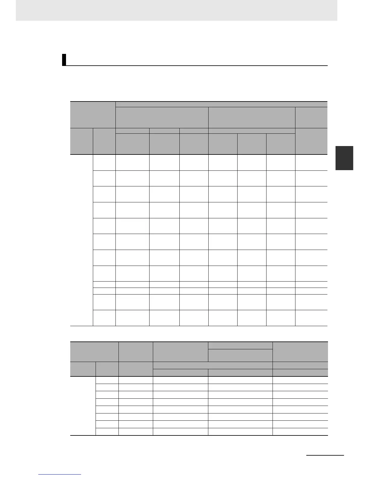
The CP1E built-in I/O terminals are allocated functions by setting parameters in the PLC Setup. Set
the PLC Setup so that each terminal is used for only one function.
z Allocating Functions to Built-in Input Terminals
z Allocating Functions to Built-in Output Terminals
Allocating Functions to Built-in I/O Terminals
Input terminal block
PLC Setup
Interrupt input settings on Built-in Input Tab
Page
High-speed counter 0 to 3 settings on Built-
in Input Tab Page
Origin search
settings on
Pulse Output
0/1 Tab Page
Terminal
block
label
Terminal
number
Normal Interrupt Quick Use
Use
Normal input
Input
interrupts
Quick-
response
Inputs
Single-
phase
(increment
pulse input)
Two-phase
(differential
phase × 4 or
up/down)
Two-phase
(pulse/direc-
tion)
CIO 0 00 Normal input 0 −−Counter 0,
increment
input
Counter 0,
phase A or up
input
Counter 0,
pulse input
−
01 Normal input 1 −−Counter 1,
increment
input
Counter 0,
phase B or
down input
Counter 1,
pulse input
−
02 Normal input 2 Interrupt
input 2
Quick-
response
input 2
Counter 2,
increment
input
Counter 1,
phase A or up
input
Counter 0,
direction
−
03 Normal input 3 Interrupt
input 3
Quick-
response
input 3
− Counter 1,
phase B or
down input
Counter 1,
direction
−
04 Normal input 4 Interrupt
input 4
Quick-
response
input 4
Counter 3,
increment
input
Counter 0,
phase Z or
reset input
Counter 0,
reset input
−
05 Normal input 5 Interrupt
input 5
Quick-
response
input 5
Counter 4,
increment
input
Counter 1,
phase Z or
reset input
Counter 1,
reset input
−
06 Normal input 6 Interrupt
input 6
Quick-
response
input 6
Counter 5,
increment
input
−−Pulse 0: Origin
input signal
07 Normal input 7 Interrupt
input 7
Quick-
response
input 7
−−−Pulse 1: Origin
input signal
08 Normal input 8 −−−−−−
09 Normal input 9 −−−−−−
10 Normal input 10 −−−−−Pulse 0, Origin
proximity input
signal
11 Normal input 11 −−−−−Pulse 1, Origin
proximity input
signal
Output terminal block
Other than
those shown at
the right
When a pulse output
instruction (SPED, ACC,
PLS2, or ORG) is executed
PLC Setup
When the PWM instruc-
tion is executed
Origin search settings on Pulse
Output 0/1 Tab Page
Terminal
block label
Terminal
number
Normal outputs
Fixed duty ratio pulse output Variable-duty-factor output
Pulse + Direction Mode Use PWM output
CIO 100
00
Normal output 0 Pulse output 0, pulse −−
01
Normal output 1 Pulse output 1, pulse − PWM output 0
02
Normal output 2 Pulse output 0, direction −−
03
Normal output 3 Pulse output 1, direction −−
04
Normal output 4 − Pulse 0, Error counter reset output −
05
Normal output 5 − Pulse 1, Error counter reset output −
06
Normal output 6 −−−
07
Normal output 7 −−−

 Loading...


