5 Installation and Wiring
5-16
CP1E CPU Unit Hardware User’s Manual(W479)
z AC Power Supply Wiring
• Use twisted-pair power supply cables to prevent noise from the power supply lines.
Adding a 1:1 isolating transformer reduces electrical noise even further.
• Consider the possibility of voltage drops and the allowable current, and always use thick power
lines.
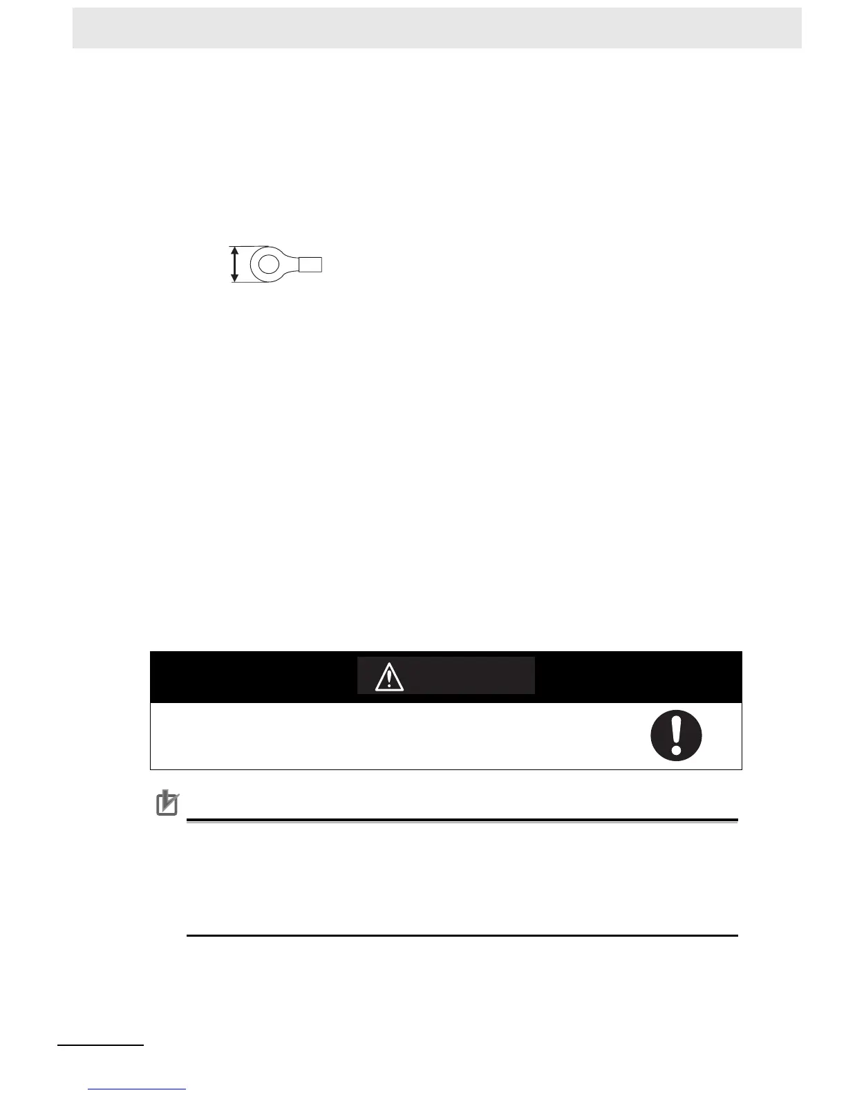
• Use round crimp terminals for AC power supply wiring.
• Use a power supply within the allowable voltage fluctuation range (85 to 264 VAC).
z Grounding
• Always ground the ground terminal to 100 Ω or less to protect against electric shock and incorrect
operation from electrical noise.
• If one phase of the power supply is grounded, connect the grounded phase to the L2/N terminal.
• The GR terminal is a ground terminal. To prevent electrical shock, use a dedicated ground line (2
mm
2
min.) of 100 Ω or less.
• The line ground terminal (LG) is a noise-filtered neutral terminal. If noise is a significant source of
errors or if electrical shocks are a problem, connect the line ground terminal (LG) to the ground
terminal (GR) and ground both with a ground resistance of 100 Ω or less.
• To prevent electrical shock when short-circuiting between the LG and GR terminals, always use a
ground of 100 Ω or less.
• Do not connect ground lines to other devices or to the frame of a building. Doing so will reverse
the effectiveness of the ground and instead have a bad influence.
z Isolation Transformer
The PLC’s internal noise isolation circuits are sufficient to control typical noise in power supply lines.
Ground noise can be further reduced by providing the power supply through a 1:1 isolating trans-
former. Do not ground the secondary coil of the transformer.
Precautions for Correct UsePrecautions for Correct Use
• Loose pieces of wires may fall in the area when wiring. To prevent these pieces from entering
into the Unit, leave the label on the top of the Unit while wiring.
• Remove the label after the completion of wiring to ensure proper heat dissipation.
• The power supply terminals are located at the top of the Unit. Do not connect a power supply
to the 24-VDC external supply terminals on the bottom of the Unit. Internal circuits may be
damaged if power is supplied to these terminals.
Tighten the AC power supply terminal screws to a torque of 0.5 N·m.
Loose screws may result in fire or malfunction.
6.2 mm max.
WARNING

 Loading...


