A-23
Appendices
CP1E CPU Unit Hardware User’s Manual(W479)
A-3 Wiring Diagrams
App
A-3-3 Expansion Units
A-3-3 Expansion Units
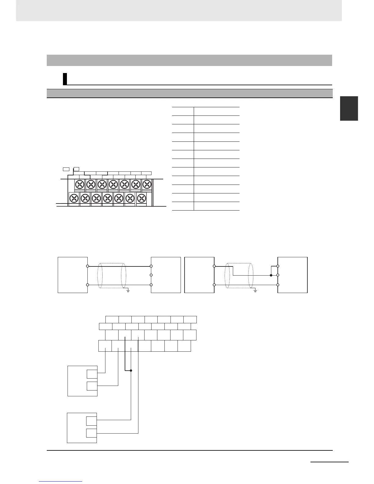
CP1W-AD041 Analog Input Unit
Wiring Diagrams
z Input Terminal Arrangement
Note For current inputs, short V IN1 to I IN1, V IN2 to I IN2, V IN3 to I IN3, and V IN4 to I IN4.
z Wiring Methods
Example:
CH
I IN1 I IN3
I IN2
VIN1
VIN2
VIN3COM1
COM2
I IN4
VIN4
COM4
NC
AG
COM3
IN
V IN1 Voltage input 1
I IN1 Current input 1
COM1 Input common 1
V IN2 Voltage input 2
I IN2 Current input 2
COM2 Input common 2
V IN3 Voltage input 3
I IN3 Current input 3
COM3 Input common 3
V IN4 Voltage input 4
I IN4 Current input 4
COM4 Input common 4
V IN
COM
I IN
V IN
COM
I IN
Analog
device with
voltage
output
Analog
Input
Unit
+
−
+
−
Analog
device with
current
output
Analog
Input
Unit
FG
FG
2-core shielded
twisted-pair cable
2-core shielded
twisted-pair cable
I IN1 VOUT2 COM2 I IN3 VIN4 COM4 AG
VIN1 COM1
IIN2
VIN3 COM3 I IN4 NC
+
–
–
Connection to
input 1 for
voltage input
Connection to
input 2 for
current input
Voltage
output
Current output
+

 Loading...


