Appendices
A-26
CP1E CPU Unit Hardware User’s Manual(W479)
Example:
CP1W-TS001/TS002/TS101/TS102 Temperature Sensor Units
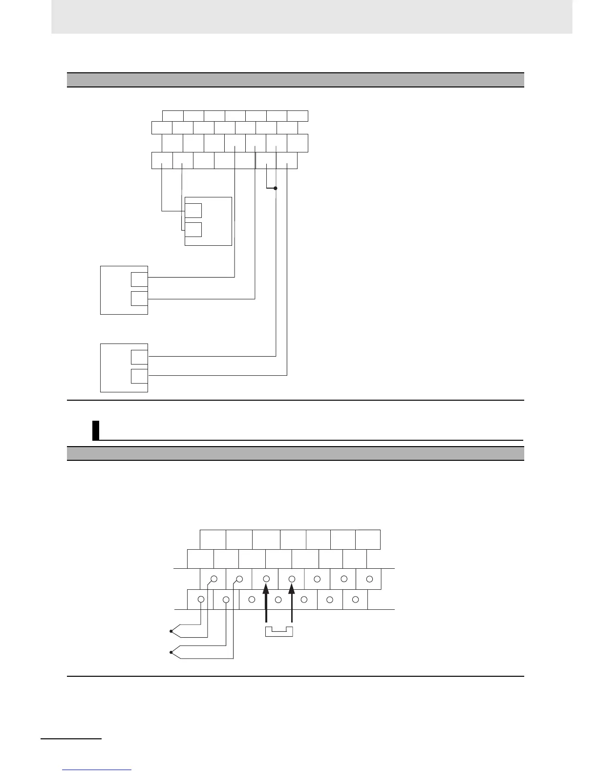
Wiring Diagrams
z Connecting a Thermocouple
• CP1W-TS001
One or two K or J thermocouples can be connected to the CP1W-TS001.
Both of the thermocouples must be of the same type and the same input range must be used for each.
Example:
Wiring Diagrams
I OUT NC NC V IN0 COM0 IIN1 AG
VOUT COM NC NC I IN0 V IN1 COM1
Connection to
input for
voltage output
Connection to
input 0 for
voltage input
Connection to
input 1 for
current input
Voltage output
Current output
Voltage input
+
–
+
+
–
–
Input 0
−
Input 0
+
NCInput 1
−
Input 1
+
NC NC NC NC
NC NC NC
Temperature input 0
Temperature input 1
Cold junction compensator

 Loading...


