3 Part Names and Functions
3-26
CP1E CPU Unit Hardware User’s Manual(W479)
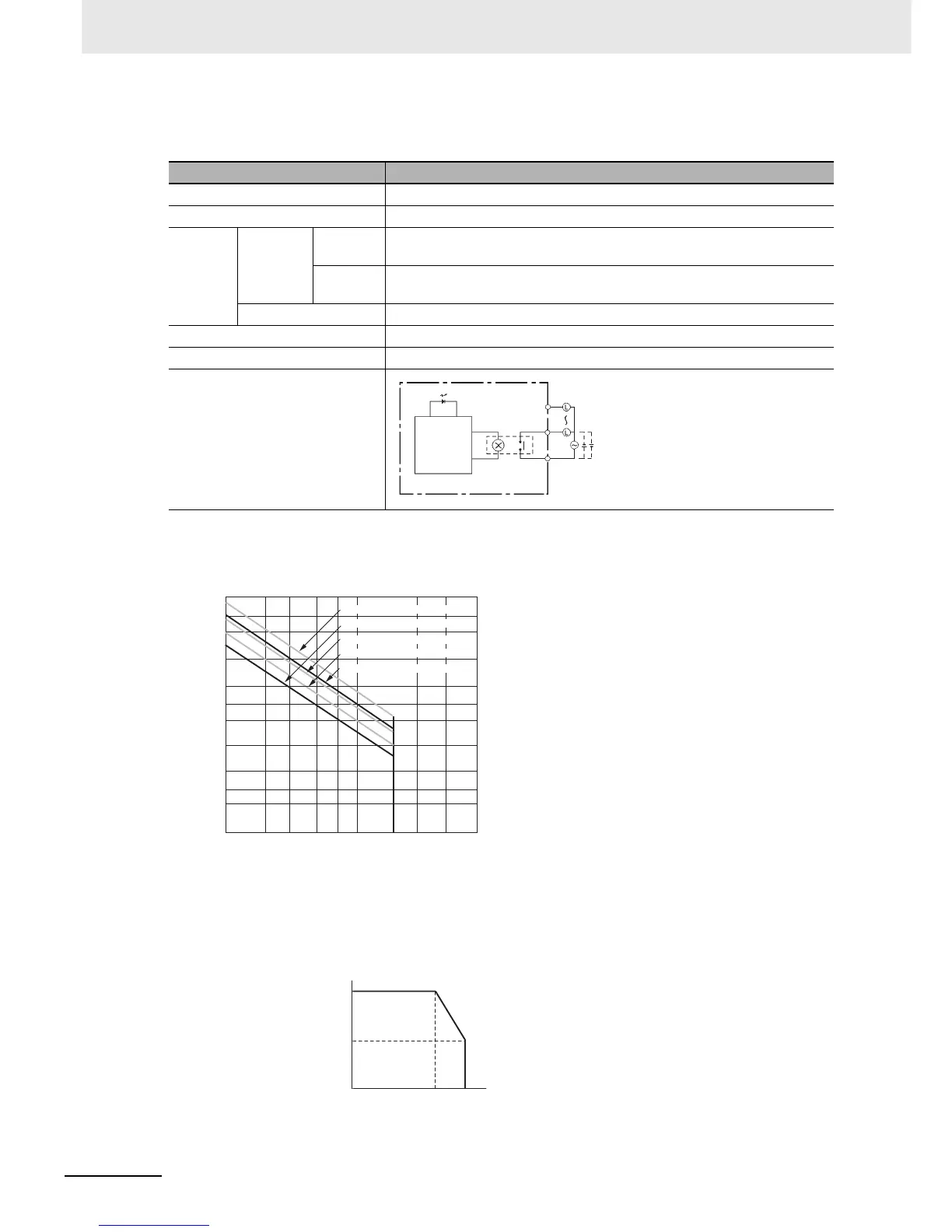
z Output Specifications for Relay Outputs
(CP1W-8ER/16ER/20EDR1/32ER/40EDR)
• Estimating the Service Life of Relays
The service life of output contacts is as shown in the following diagram.
• Restrictions of CP1W-16ER/32ER
In addition to the above restrictions, limit the output load current so that it satisfies the following derat-
ing curve.
Item Specification
Maximum switching capacity 2 A 250 VAC (cosφ = 1), 2 A 24 VDC (4 A/common)
Minimum switching capacity 10 mA 5 VDC
Service
life of
relay
Electrical Resistive
load
150,000 operations (24 VDC)
Inductive
load
100,000 operations (240 VAC, cosφ = 0.4)
Mechanical 20,000,000 operations
ON response time 15 ms max.
OFF response time 15 ms max.
Circuit configuration
CP1W-16ER/32ER
COM
OUT
OUT
Output indicator
Internal
circuits
250 VAC, 2A,
24 VDC, 2 A
max.
Contact current (A)
300
200
100
50
30
20
5
3
2
10
0.1 0.2 0.3 0.5 0.7 1 3 5
120-VAC resistive load
24 VDC, τ = 7 ms
120 VAC COSφ = 0.4
240 VAC COSφ = 0.4
24-VDC/240-VAC resistive load
Life (× 10
4
)
Switching frequency: 1,800 operations/hour
2
50
100
5543
Ambient temperature (˚C)
Output load current(%)

 Loading...


