107
Pulse I/O Board Section 2-2
Single-Phase Fixed Duty
Factor Pulse Outputs
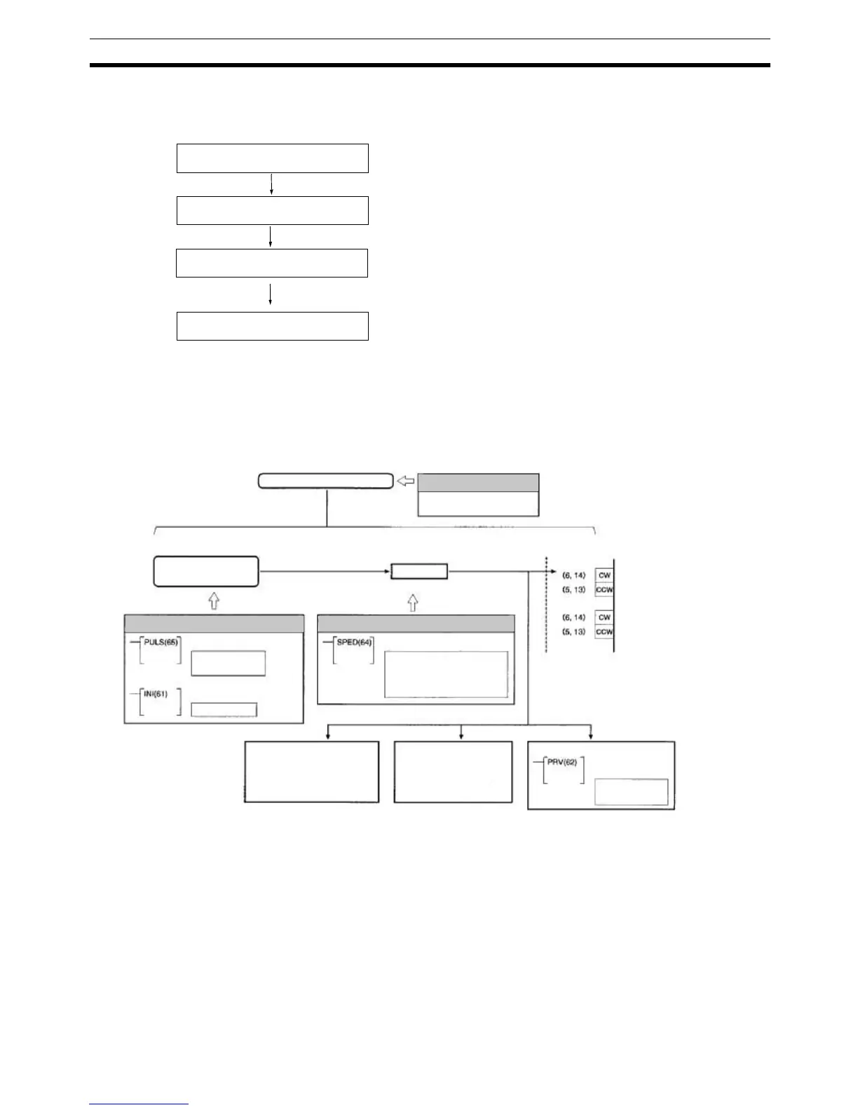
The following flowchart shows the procedure for using PULS(65) and
SPED(64) to perform single-phase fixed duty factor pulse outputs without
acceleration or deceleration.
Determine pulse output port.
Wire output.
PC Setup
(DM 6611/DM 6643/DM 6644)
Ladder Program
Pulse output port 1 or 2.
Output:
CW/CCW with/without 1.6 k
Ω resistance.
Power supply for output: 5/24 V DC
Port Mode Setting (DM 6611): Sets to High-speed Counter
Mode (0000 Hex) or Simple Positioning Mode (0001 Hex).
Operation settings for ports 1 and 2 (DM 6643/DM 6644):
Set to fixed duty factor.
SET PULSES, PULS(65):
Set number of output pulses for each port.
SPEED OUTPUT, SPED(64):
Port-specific pulse output control without acceleration/
deceleration.
MODE CONTROL, INI(61):
Stop pulse output to a specified port.
HIGH-SPEED COUNTER PV READ, PRV(62):
Read pulse output status of a specified port.
Fixed duty factor pulse output
Single-phase fixed duty
factor pulse output without
acceleration/deceleration
SPEED OUTPUT
No. of pulses out-
put (8-digit BCD)
MODE CONTROL
Mode: Continuous/Independent
Unit: 1 Hz or 10 Hz
Target: 10 Hz to 50 kHz
Starting pulse output
Each cycle
Each execution
Pulse output status
Port 1: AR 05
Port 2: AR 06
Pulse output PV
Port 1: IR 237, IR 236
Port 2: IR 239, IR 238
HIGH-SPEED COUNT-
ER PV READ
Pulse output sta-
tus read
Pulse I/O Board
− Pulse output
− Port 1 (CN1)
− Pulse output
− Port 2 (CN2)
Stopping output
Output
Each cycle
Single-phase Fixed Duty Factor Pulse Output without Acceleration/Deceleration
PC Setup
Bits 12 to 15 of
DM 6643/DM 6644 set to 0.
Ladder Program
SET PULSES
Ladder Program