162
SR Area Section 3-3
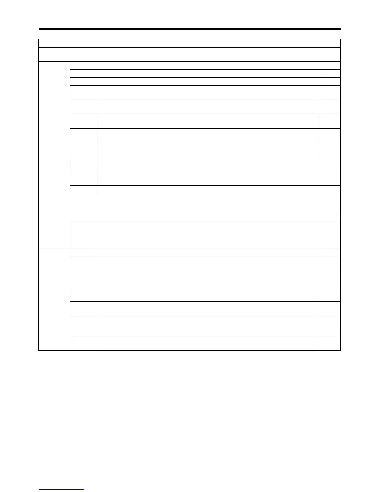
SR 25211
(Forced Status Hold Bit)
When the forced set/reset status is cleared, the bits that were forced will be
turned ON or OFF as follows:
Forced set cleared: Bit turned ON
Forced reset cleared: Bit turned OFF
All force-set or force-reset bits will be cleared when the PC is switched to RUN
mode unless DM 6601 in the PC Setup has been set to maintain the previous
status of the Forced Status Hold Bit when power is turned ON. This setting
can be used to prevent forced status from being cleared even when power is
turned ON.
Turn this bit ON and OFF from a Programming Device.
SR 25212
(I/O Hold Bit)
When this bit is ON, the status of bits in the IR and LR areas will be retained
when the PC is switched from PROGRAM to RUN or MONITOR mode. (If the
SR253 15 First Cycle Flag
Turns ON for 1 cycle at the start of operation.
---
SR254 00 1-minute Clock Pulse (30 seconds ON; 30 seconds OFF) ---
01 0.02-second Clock Pulse (0.01 second ON; 0.01 second OFF) ---
02 to 03 Not used.
04 Overflow (OF) Flag
Turns ON when the result of a calculation is above the upper limit of signed binary data.
328
05 Underflow (UF) Flag
Turns ON when the result of a calculation is below the lower limit of signed binary data.
328
06 Differential Monitor Complete Flag
Turns ON when differential monitoring is complete.
147
07 STEP(08) Execution Flag
Turns ON for 1 cycle only at the start of process based on STEP(08).
231
08 HKY(––) Execution Flag
Turns ON during execution of HKY(––).
431
09 7SEG(88) Execution Flag
Turns ON during execution of 7SEG(88).
424
10 DSW(87) Execution Flag
Turns ON during execution of DSW(87).
427
11 to 12 Not used.
13 Communications Unit Error Flag
Turns ON when an error occurs in a Communications Unit. This flag mirrors the opera-
tion of the Communications Unit Error Flag (AR 0011).
427
14 Not used.
15 Inner Board Error Flag
Turns ON when an error occurs in an Inner Board mounted in slot 1 or slot 2. The error
code for slot 1 is stored in AR 0400 to AR 0407 and the error code for slot 2 is stored in
AR 0408 to AR 0415.
---
SR255 00 0.1-second Clock Pulse (0.05 second ON; 0.05 second OFF) ---
01 0.2-second Clock Pulse (0.1 second ON; 0.1 second OFF) ---
02 1.0-second Clock Pulse (0.5 second ON; 0.5 second OFF) ---
03 Instruction Execution Error (ER) Flag
Turns ON when an error occurs during execution of an instruction.
---
04 Carry (CY) Flag
Turns ON when there is a carry in the results of an instruction execution.
---
05 Greater Than (GR) Flag
Turns ON when the result of a comparison operation is “greater.”
---
06 Equals (EQ) Flag
Turns ON when the result of a comparison operation is “equal,” or when the result of an
instruction execution is 0.
---
07 Less Than (LE) Flag
Turns ON when the result of a comparison operation is “less.”
---
Word Bit(s) Function Page