245
Timer and Counter Instructions Section 5-16
The following diagram shows the structure of a target value comparison table
for use with the Pulse I/O Board’s high-speed counters 1 or 2 set for ring
counting. Input the target values in ascending or descending order.
The ring value specifies the number of points in the ring and the maximum
count value (ring value = max. count value+1). The ring value can be 0 to 65,
000. Do not change the ring value while a comparison is in progress.
The following diagram shows the structure of a target value comparison table
for use with the Absolute Encoder Interface Board’s high-speed counters 1
and 2. Input the target values in ascending or descending order. The number
of target values can be 0001 to 0048.
Note 1. The subroutine number can be F000 to F255 to activate the subroutine
when decrementing and can be 0000 to 0255 to activate the subroutine
when incrementing.
2. Allow an interval of at least 0.2 ms for interrupt processing when setting the
target value for high-speed counters 1 and 2.
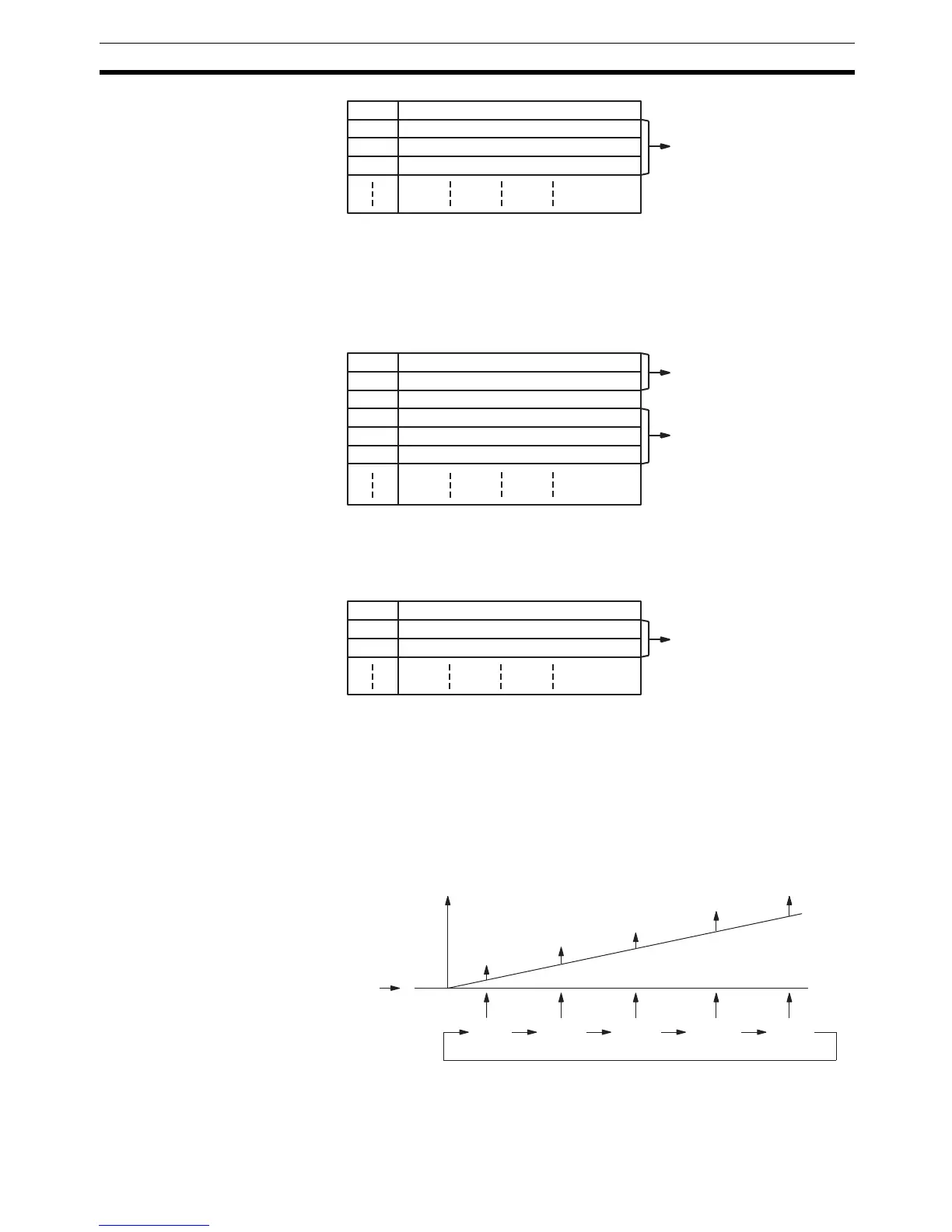
Target Value Comparison Operation
The following diagram illustrates the operation of target value comparisons for
target values 1 through 5 set consecutively in the comparison table.
As illustrated above, the current count is compared with each target value in
the order that they are registered in the target value comparison table. When
the count is the same as the current target value, an interrupt is generated,
TB Number of target values (BCD)
TB+1 Target value #1, lower 4 digits (BCD)
TB+2 Target value #1, upper 4 digits (BCD)
TB+3 Subroutine number (See note 1.)
One target value setting
TB Ring value, lower 4 digits (BCD)
TB+1 Ring value, upper 4 digits (BCD)
TB+2 Number of target values (BCD)
TB+3 Target value #1, lower 4 digits (BCD)
TB+4 Target value #1, upper 4 digits (BCD)
TB+5 Subroutine number (See note 1.)
One target value setting
Ring value setting
TB Number of target values (BCD)
TB+1 Target value #1 (BCD)
TB+2 Subroutine number (See note 1.)
One target value setting
Initial
value
Count
Interrupts
Target
1
Target
2
Target
4
Target
3
Target
5