246
Timer and Counter Instructions Section 5-16
and comparison starts with the next target value. When all target values in the
comparison table have been matched and interrupts for them generated, the
target value is reset to the first target value in the table and the operation is
repeated.
Range Comparison
A range comparison table contains 8 ranges which are defined by an 8-digit
lower limit and an 8-digit upper limit, as well as their corresponding subroutine
numbers. The corresponding subroutine is called and executed when the PV
falls within a given range. (When interrupt processing is not required, an
undefined subroutine number may be entered.)
Always set 8 ranges. If fewer than 8 ranges are needed, set the remaining
subroutine numbers to FFFF. If more than 8 ranges are needed, another com-
parison instruction such as BCMP(68) can be used to compare ranges with
the high-speed counter PVs in IR 230 through IR 235. Bear in mind that these
words are refreshed just once each cycle.
There are flags in the AR area which indicate when a high-speed counter’s PV
falls within one or more of the 8 ranges. The flags turn ON when a PV is within
the corresponding range.
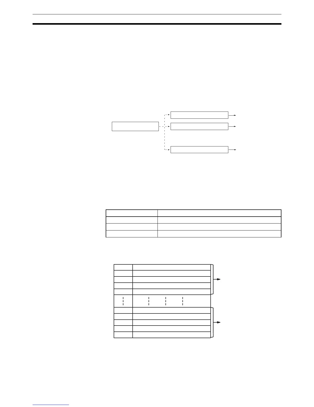
The following diagram shows the structure of a range comparison table for
use with the CPU Unit’s built-in high-speed counter 0 or the Pulse I/O Board’s
high-speed counters 1 or 2 set for linear counting.
The following diagram shows the structure of a range comparison table for
use with the Pulse I/O Board’s high-speed counters 1 or 2 set for ring count-
ing. The ring value specifies the number of points in the ring and the maxi-
mum count value (ring value = max. count value+1); the setting range fro the
Counter AR area flags
High-speed counter 0 AR 1100 to AR 1107 correspond to ranges 1 to 8.
High-speed counter 1 AR 0500 to AR 0507 correspond to ranges 1 to 8.
High-speed counter 2 AR 0600 to AR 0607 correspond to ranges 1 to 8.
High-speed counter PV
Execute subroutine.
Execute subroutine.
Execute subroutine.
•
•
•
•
•
•
Within
range
Lower limit 1 ↔ Upper limit 1
Lower limit 2 ↔ Upper limit 2
Lower limit 8 ↔ Upper limit 8
TB Lower limit #1, lower 4 digits (BCD)
TB+1 Lower limit #1, upper 4 digits (BCD)
TB+2 Upper limit #1, lower 4 digits (BCD)
TB+3 Upper limit #1, upper 4 digits (BCD)
TB+4 Subroutine number (See note 1.)
TB+35 Lower limit #8, lower 4 digits (BCD)
TB+36 Lower limit #8, upper 4 digits (BCD)
TB+37 Upper limit #8, lower 4 digits (BCD)
TB+38 Upper limit #8, upper 4 digits (BCD)
TB+39 Subroutine number (See note 1.)
First range setting
Eighth range setting