250
Timer and Counter Instructions Section 5-16
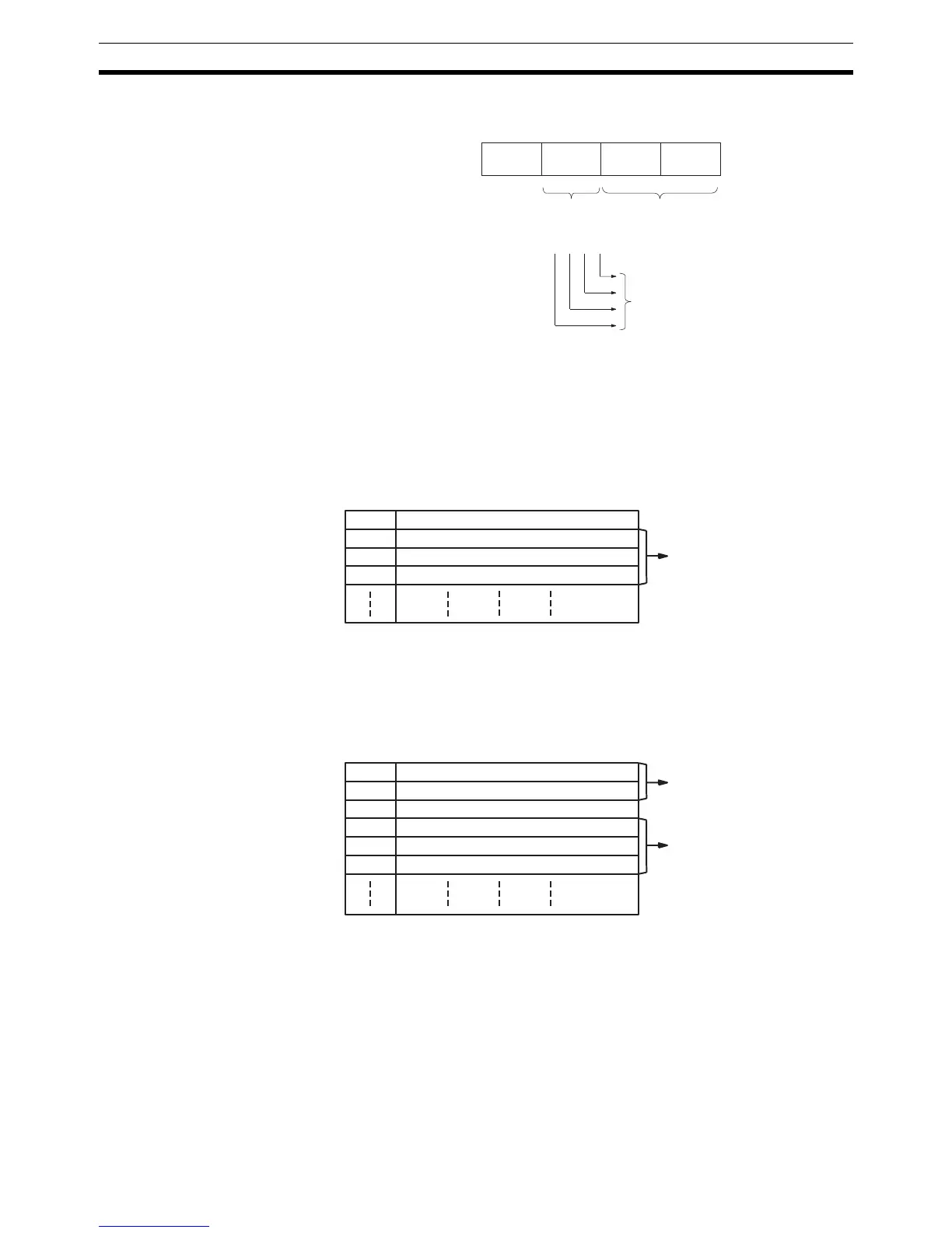
Note Bit patterns 1 to 48 are configured as follows:
Target value comparisons are performed one item at a time in order of the
comparison table. When the PV reaches the first target value in the table, the
bit pattern is output to the allocated IR word and comparison continues to the
next value in the table. When processing has been completed for the last tar-
get value in the table, comparison returns to the first value in the table and the
process is repeated.
The following diagram shows the structure of a target value comparison table
for use with high-speed counters 1 to 4 when set for linear counting.
The following diagram shows the structure of a target value comparison table
for use with high-speed counters 1 to 4 when set for ring counting. Input the
target values in ascending or descending order.
The ring value specifies the number of points in the ring and the maximum
count value (ring value = max. count value+1). Do not change the ring value
while a comparison is in progress.
Target values 1 to 48 and bit patterns 1 to 48 are stored in the comparison
table. Bits 0 to 7 of the bit pattern are stored as the internal bit pattern. Bits 8
to 11 are stored as the external bit pattern, the logical OR of these bits is cal-
culated for the four high-speed counters, and the result is output to external
outputs 1 to 4.
IR 208 to IR 211 or
IR 240 to IR 243
External
bit pattern
Internal bit
pattern (8 bits)
Takes the logical OR of the
same 4 bits in IR 208 to IR 211
or IR 240 to IR 243 and out-
puts the result to the 4 external
outputs.
11 87 0
TB Number of target values (BCD)
TB+1 Target value #1, lower 4 digits (BCD)
TB+2 Target value #1, upper 4 digits (BCD)
TB+3 Bit pattern #1
One target value setting
TB Ring value, lower 4 digits (BCD)
TB+1 Ring value, upper 4 digits (BCD)
TB+2 Number of target values (BCD)
TB+3 Target value #1, lower 4 digits (BCD)
TB+4 Target value #1, upper 4 digits (BCD)
TB+5 Bit pattern #1
One target value setting
Ring value setting