251
Timer and Counter Instructions Section 5-16
The following example shows how the bit patterns for high-speed counters 1
to 4 are ORed to produce the resulting output at the external outputs.
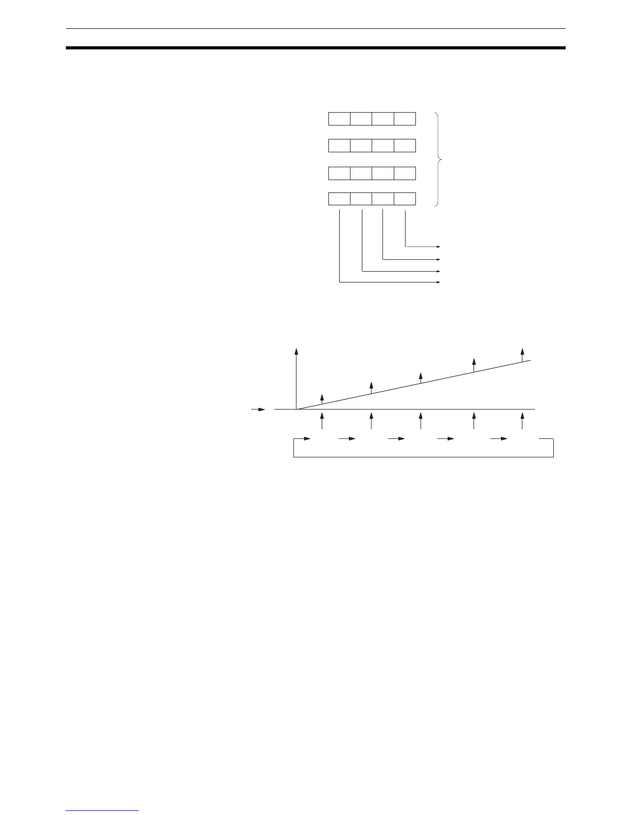
Target Value Comparison Operation
The following diagram illustrates the operation of target value comparisons for
target values 1 through 5 set consecutively in the comparison table.
As illustrated above, the current count is compared with each target value in
the order that they are registered in the target value comparison table. When
the count is the same as the current target value, the registered bit pattern is
output to the allocated IR word, and comparison starts with the next target
value. When all target values in the comparison table have been matched and
their bit patterns have been output, the target value is reset to the first target
value in the table and the operation is repeated.
Range Comparison
A range comparison table contains 8 ranges which are defined by an 8-digit
lower limit and an 8-digit upper limit, as well as the bit pattern. The registered
bit pattern is output to the allocated IR word when the PV falls within a given
range. The High-speed Counter Board does not generate interrupts; the reg-
istered bit pattern is reflected in the allocated IR word and at the external out-
puts.
High-speed counter 1 comparison results (IR 208 or IR 240)
High-speed counter 2 comparison results (IR 209 or IR 241)
High-speed counter 3 comparison results (IR 210 or IR 242)
High-speed counter 4 comparison results (IR 211 or IR 243)
Slot 1 Slot 2
Calculate the logical
OR and output.
External output 1: ON
External output 2: ON
External output 3: ON
External output 4: OFF
Bit
0 0 0 1
11 10 09 08
0 0 1 0
11 10 09 08
0 1 0 0
11 10 09 08
0 0 0 0
11 10 09 08
Initial
value
Count
Bit pattern output
Target
1
Target
2
Target
4
Target
3
Target
5