252
Timer and Counter Instructions Section 5-16
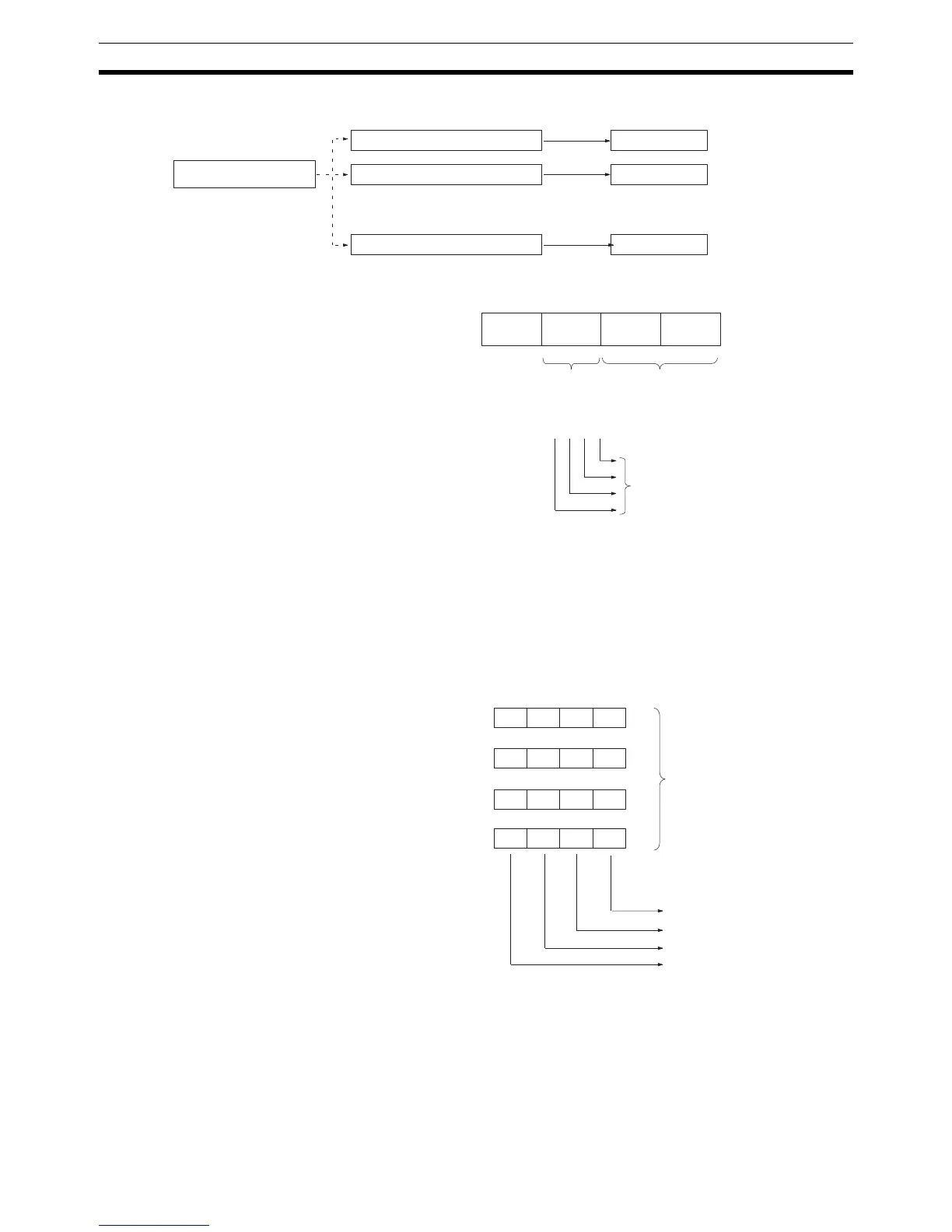
Note Bit patterns 1 to 16 are configured as follows:
Register a lower limit, upper limit, and bit pattern for each range (1 to 16) in
the range comparison table. Bits 0 to 7 of the bit pattern are stored as the
internal bit pattern. Bits 8 to 11 are stored as the external bit pattern, the logi-
cal OR of these bits is calculated for the four high-speed counters, and the
result is output to external outputs 1 to 4.
The following example shows how the bit patterns for high-speed counters 1
to 4 are ORed to produce the resulting output at the external outputs.
High-speed counter PV
•
•
•
•
•
•
Within
range
Compare
Bit pattern 1
Bit pattern 2
Bit pattern 16
11 0
(see note)
(see note)
(see note)
Lower limit 1 ↔ Upper limit 1
Lower limit 2 ↔ Upper limit 2
Lower limit 16 ↔ Upper limit 16
IR 208 to IR 211 or
IR 240 to IR 243
External
bit pattern
Internal bit
pattern (8 bits)
Takes the logical OR of the
same 4 bits in IR 208 to IR 211
or IR 240 to IR 243 and out-
puts the result to the 4 external
outputs.
11 87 0
High-speed counter 1 comparison results (IR 208 or IR 240)
High-speed counter 2 comparison results (IR 209 or IR 241)
High-speed counter 3 comparison results (IR 210 or IR 242)
High-speed counter 4 comparison results (IR 211 or IR 243)
Slot 1 Slot 2
Calculate the logical
OR and output.
External output 1: ON
External output 2: ON
External output 3: ON
External output 4: OFF
Bit
0 0 0 1
11 10 09 08
0 0 1 0
11 10 09 08
0 1 0 0
11 10 09 08
0 0 0 0
11 10 09 08