534
Memory Areas Appendix C
Flags/Bits for Inner Boards (AR 05 and AR 06)
High-speed Counter Board Slot 2 Flags/Bits (AR 05 to AR 06)
AR 04 00 to 07 Slot 1 Inner Board Error Code (Hex)
00: Normal
01, 02: Hardware error
04: Serial Communications Board error
08 to 15 Slot 2 Inner Board Error Code (Hex)
00: Normal
01, 02: Hardware error
03: PC Setup error
04: PC stopped during pulse output or A/D (D/A) conversion error
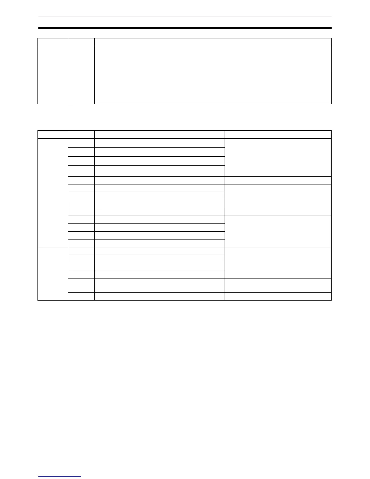
Word Bit(s) Function Operation
AR 05 00
High-speed Counter 1 Reset Bit
Z Phase and software reset
0: Z-phase reset disabled
1: Z-phase reset enabled
Software reset only
0: Software reset disabled
0→1: Executes software reset
01
High-speed Counter 2 Reset Bit
02
High-speed Counter 3 Reset Bit
03
High-speed Counter 4 Reset Bit
04 to 07 Not used. ---
08 High-speed Counter 1 Comparison Stop Bit 0→1: Starts comparison.
1→0: Stops comparison.
09 High-speed Counter 2 Comparison Stop Bit
10 High-speed Counter 3 Comparison Stop Bit
11 High-speed Counter 4 Comparison Stop Bit
12 High-speed Counter 1 Stop Bit 0: Continues operation.
1: Stops operation.
13 High-speed Counter 2 Stop Bit
14 High-speed Counter 3 Stop Bit
15 High-speed Counter 4 Stop Bit
AR 06 00 External Output 1 Force-set Bit 0: Not valid
1: Forced ON
01 External Output 2 Force-set Bit
02 External Output 3 Force-set Bit
03 External Output 4 Force-set Bit
04 External Output Force-set Enable Bit 0: Force-setting of outputs 1 to 4 disabled
1: Force-setting of outputs 1 to 4 enabled
05 to 15 Not used. ---
Word Bit(s) Function