37
Interrupt Functions Section 1-4
Procedure Follow the steps outlined below when using high-speed counter 0 (the CPU
Unit’s built-in high-speed counter.)
1,2,3... 1. Determine the input mode (differential phase mode or incrementing mode)
and reset method (phase-Z signal + software reset, or software reset) to
be used.
2. Determine the interrupt specifications.
a) No interrupt (Read high-speed counter PV or range comparison re-
sults.)
b) Use target-value interrupts or range-comparison interrupts.
3. Wire the inputs. (Refer to the CQM1H Operation Manual for details.)
4. Make PC Setup settings in DM 6642. (See page 39 for more details.)
a) Set 01 in the leftmost byte to indicate that high-speed counter 0 will be
used.
b) Set the input mode (differential phase mode or incrementing mode.)
c) Set the reset method (phase-Z signal + software reset, or software re-
set.)
Note High-speed counter 0 cannot be used while interval timer 2 is being
used. (The setting in the leftmost byte of DM 6642 determines wheth-
er high-speed counter 0 or interval timer 2 can be used.)
5. Program the associated program sections.
a) Use CTBL(63) to register the comparison table and start comparison.
b) Use INI(61) to change the high-speed counter PV or start comparison.
c) Use PRV(62) to read the high-speed counter PV, comparison status,
or comparison results.
d) Write an interrupt subroutine within SBN(92) and RET(93) (only when
using the high-speed counter 0 interrupt.)
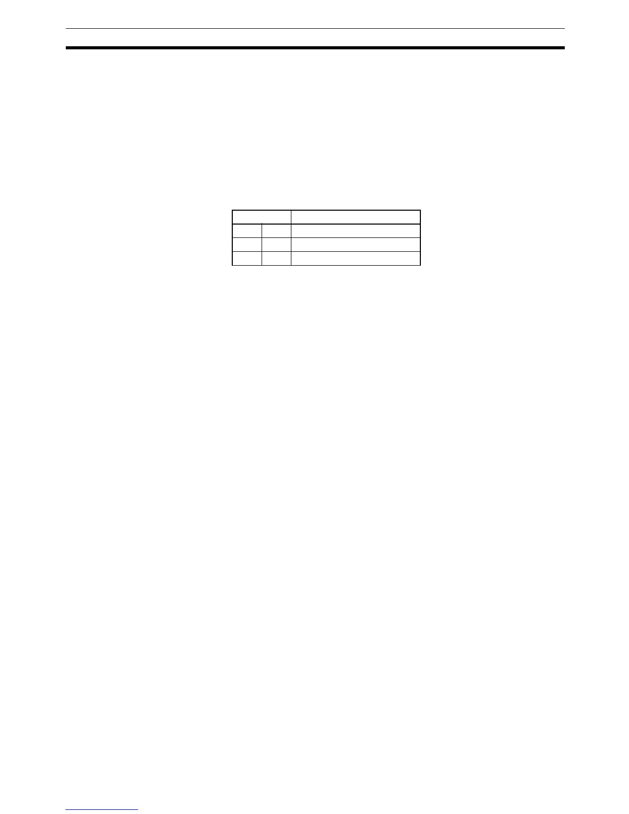
Terminal Corresponding bit address
B2 IN4 IR 00004
A2 IN5 IR 00005
B3 IN6 IR 00006