38
Interrupt Functions Section 1-4
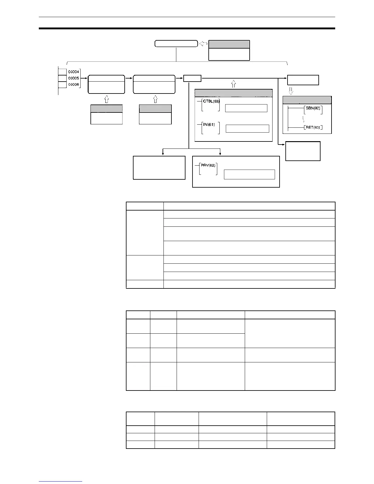
The following instructions are used to control high-speed counter operation.
The following flags and control bits are used to monitor and control high-
speed counter operation.
Wiring Depending on the input mode, the input signals from the pulse encoder to the
CPU Unit’s input terminal are as shown below.
High-speed counter 0
Encoder
inputs
When using interrupts.
Each cycle
Counter PV
SR 231 and SR 230
Input mode
Differential phase
Incrementing
Reset method
Phase-Z + software
Software
Count
MODE CONTROL
Register table.
Start comparison.
HIGH-SPEED COUNTER
PV READ
Change counter PV.
Start/stop comparison.
Read counter PV.
Read status of comparison.
AR 1100 to
AR 1107
DM 6642 bits
08 to 15
Each execution
Execute specified
subroutine.
PC Setup PC Setup
Ladder Program
REGISTER COMP TABLE
PC Setup
Generate
interrupt.
Interrupt Subroutine
Range
comparison
results
DM 6642 bits
04 to 07
DM 6642 bits
00 to 03
Instruction Control function
CTBL(63) Register a target value comparison table and start comparison.
Register a range comparison table and start comparison.
Register a target value comparison table.
(Start comparison with INI(61).)
Register a range comparison table.
(Start comparison with INI(61).)
INI(61) Start comparison with registered comparison table.
Stop comparison.
Change high-speed counter PV.
PRV(62) Read high-speed counter PV.
Word Bits Name Function
SR 230 00 to 15 High-speed Counter 0 PV
(rightmost 4 digits)
Contains the present value of high-
speed counter 0 (the CPU Unit’s
built-in high-speed counter.)
SR 231 00 to 15 High-speed Counter 0 PV
(leftmost 4 digits)
SR 252 00 High-speed Counter 0
Reset Bit
Resets the PV of high-speed
counter 0.
AR 11 00 to 07 High-speed Counter 0
Range Comparison Flags
Indicate the range comparison
results for high-speed counter 0.
0: Range condition not satisfied.
1: Range condition satisfied.
Terminal Allocated bit
address
Differential phase mode Incrementing mode
B2 (IN4) 00004 Encoder phase-A Pulse count input
A2 (IN5) 00005 Encoder phase-B ---
B3 (IN6) 00006 Encoder phase-Z Reset input