70
High-speed Counter Board Section 2-1
Numeric Ranges The values counted by high-speed counters 1 to 4 can be counted using the
following two range settings:
Ring Mode
In Ring Mode, the maximum value of a numerical range can be set using
CTBL(63), and when the count is increment beyond this maximum value, it
returns to zero. The count never becomes negative. Similarly, if the count is
decremented from 0, it returns to the maximum value. The number of points
on the ring is determined by setting the maximum value (i.e., the ring value) to
a value between 1 and 8388607 BCD or between 1 and 7FFFFFFF Hex.
When the maximum value is set to 8388607, the range will be 0 to 8388607
BCD.
Linear Mode
In Linear Mode, the count range is always –8388608 to 8388607 BCD or
F8000000 to 07FFFFFF Hex. If the count decrements below –8388608 BCD
or F8000000 Hex, an underflow is generated, and if it increments above
8388607 BCD or 07FFFFFF Hex, an overflow is generated.
If an overflow occurs, the PV of the count will remain at 08388607 BCD or
07FFFFFF Hex, and if an underflow occurs, it will remain at F8388608 BCD or
F8000000 Hex. In either case, counting and comparison will stop, but the
comparison table will be retained in memory. The PV Overflow/Underflow Flag
shown below will turn ON to indicate the underflow or overflow.
When restarting the counting operation, use the reset methods given below to
reset high-speed counters 1 and 2. (Counters will be reset automatically when
program execution starts and finishes.)
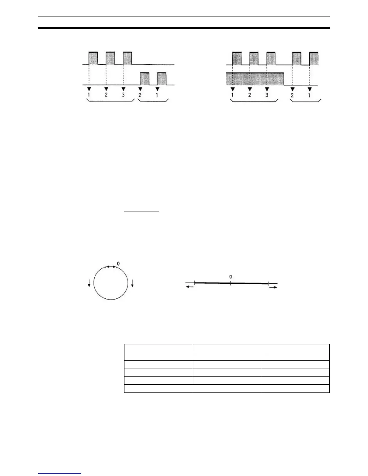
Up/Down Mode
Encoder input A
(UP input)
Encoder input B
(DOWN input)
Decrement
Pulse/Direction Mode
Encoder input A
(Pulse input)
Encoder input B
(Direction input)
DecrementIncrement Increment
Ring Mode
Max. count value
(Ring value)
Linear Mode
Decrement Increment
Underflow Overflow
F8000000 Hex
−8388608 BCD
07FFFFFF Hex
Counter PV Overflow/Underflow Flag
Slot 1 Slot 2
High-speed counter 1 IR 20814 IR 24014
High-speed counter 2 IR 20914 IR 24114
High-speed counter 3 IR 21014 IR 24214
High-speed counter 4 IR 21114 IR 24314