Manual Version e1-4.3.0.ae-R3. Page
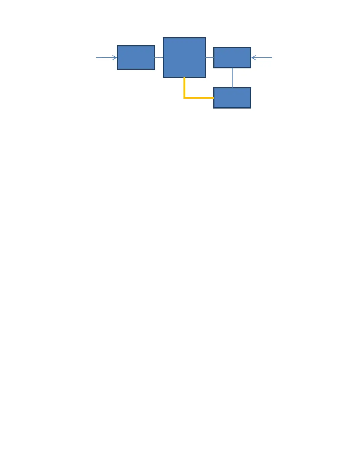
Figure 1. System Overview. Blue, thin lines indicate electrical and
orange, thick, indicates vacuum connections.
The top level diagram showing the major components of the system is shown in Figure 1. Within these
main components are:
• XeF
2
source bottle (supplied by customer) contains solid XeF
2
, a white crystalline substance
much resembling rock salt. At room temperature, the vapor pressure of XeF
2
is 3.9 Torr.
• N
2
source: supplies N
2
gas (supplied by customer) for venting and purging the process
chamber, and combining with XeF
2
for etching.
• Expansion chamber: sublimated XeF
2
and nitrogen gas collect in the expansion chamber
before entering the process chamber. The pressure of XeF
2
and the pressure of N
2
are
selected by the user, and gases are allowed into the process chamber only when these
pressures have been achieved.
• Process chamber: this is where the etching occurs for the amount of time specified by the user.
When the etch cycle time is up, gas is pumped out and another etch cycle begins.
• Vacuum pump: this pumps gases out of both the process chamber and the expansion
chamber.
• N
2
regulator in the gas box which controls the pressure of the N
2
for the venting of the main
chamber and N
2
filling of the expansion chamber. Higher pressures lead to faster fill rates but
may lead to reduced fill accuracy or in the case of venting, disturbances to the sample.
• Needle valve for accurately adjusting the flow rate of N
2
for the Expansion chamber is located
on the left side of the system, on the gas panel. It should not need to be adjusted for normal
use, and should remain partially open. Regulation of XeF
2
and nitrogen (N
2
) is automatically
accomplished through a series of computer controlled valves. The needle valve provides fine
control of the flow rate of N
2
whereas the regulator provides gross control.
• Displays of pressure in the expansion chamber and process chamber are located on the
computer screen.
This manual gives physical details of the services and ambient conditions required to accommodate the
Xactix e1 Series xenon difluoride etching system and to allow it to produce the high performance for
which it is designed.
It must be emphasized that the time and expense devoted to proper site preparation will be rewarded
by the consequent trouble-free, consistent operation and the resulting reduction in downtime.
Etch
Module
PC