3.1 MAIN PARTS
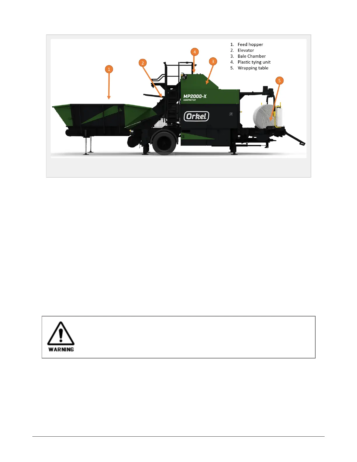
Figure 3.1 :
The compactor main parts
3.1.1 Principle of operation
The material is loaded into the feed hopper using a wheel loader, or directly by a conveyor belt. The mater-
ial is then transported by the elevator into the chamber. The amount and speed is controlled by an ultra-
sonic sensor as well as settings in the display unit. All functions and settings may be adjusted depending
on the characteristics of the material being baled.
When the material has been shaped to a compact bale, several layers of net or film is laid on the bale by
the net/film system. The net/film ensures that the bale maintains its shape during the transport to the
wrapper. The chamber door is opened automatically and the bale is transported to the wrapper by the sub
conveyor. The chamber door closes and the baling immediately resumes. If there is any spillage, this will be
recycled back to the elevator by the sub conveyor.
The wrapping starts as soon as the bale is detected on the wrapping table. Parameters such as chamber
pressure and the number of layers of film may be set on the display unit. During normal operation, the
machine runs on the automatic sequence. The operator(s) main task is to ensure that there is a sufficient
amount of material in the hopper and that the finished bales are moved away from the bale drop zone. The
operator shall also check for leaks and listen for unusual sounds while performing tasks as refilling the
plastic magazine.
3.2 HYDRAULICS
The compactors hydraulic system operates with high pressure. Check all hoses and con-
nections for damage. Replace damaged parts immediately. When adjusting the machines
hydraulic valves, being within the wrappers area of movement is not allowed. Take cautions
when adjusting the valves, as the wrapper arms speed may change rapidly. Make yourself famil-
iar with all the functions of the machine.
The default setting of the machine is done during the test run at the factory. Before performing any
changes or testing on the machine, the hydraulic oil must have reached normal work temperature. This is
because certain functions are affected by the oils viscosity and may respond differently if the oil is cold.
For recommended oil types to be used, see section 8.6.1 "Hydraulics" . In the description of how to adjust
the machines hydraulic valves, the valves are referred to by valve numbers. See overview in section 11.2
"Valve overview".
3 SETTINGS AND HYDRAULIC ADJUSTMENTS 23