17A ENGINE TIMING
To check the engine timing mark17A-05
Special tools:
Universal timing tool, MS.67B
Drive adaptor for use with MS.67B, PD.67-2
Pointer for use with MS.67B, PD.67-4
Distance piece for use with MS.67B, PD.67-5
Note: The mark was removed from the timing case
when the Bosch EPVE Pump with a locking screw
was introduced.
1 Set the piston of number 1 cylinder to TDC on
the compression stroke, operation 17A-01.
2 Remove the fuel injection pump and its joint,
operation 20A-06A.
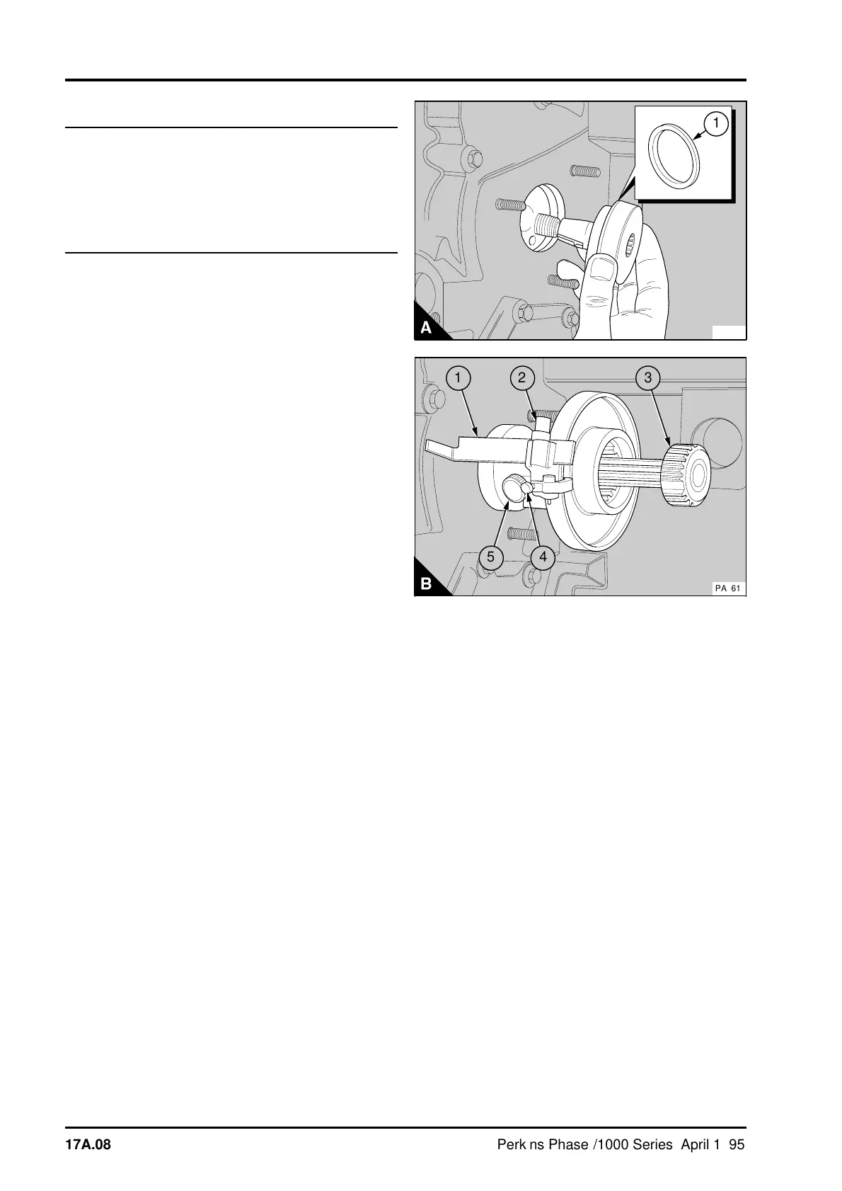
3 Fit the distance piece PD.67-5 (A1) to the timing
tool adaptor PD.67-2. Align the key in the adaptor
with the keyway in the gear of the fuel pump and fit
the adaptor to the gear (A). Ensure that the
distance piece is against the rear face of the timing
case. Secure the adaptor to the gear with the nut
supplied with the adaptor.
4 Loosen the screw (B4) on the timing tool
MS.67B. Set the timing tool to the correct engine
check angle, see data and dimensions, and tighten
the screw. Loosen the screw (B5) and fit the
splined shaft (B3) into the timing tool (B). Loosen
the screw (B2). Fit the 90° pointer PD.67-4 (B1)
and tighten the screw.
5 Fit the splined shaft of the timing tool to the
adaptor. Slide the timing tool along the splined shaft
until it is against the adaptor and tighten the screw
(B5).
6 Loosen the screw (B2). Slide the pointer forward
until the flat face is against the rear face of the
timing case and tighten the screw. If the mark on
the timing case is correct, the mark will align with
the top edge of the pointer (B1). If the mark is not
correct, remove the timing tool and eliminate the
mark on the timing case. Fit the timing tool. Ensure
that the pointer is against the timing case and make
a new mark on the timing case along the top
straight edge of the pointer.
7 Remove the timing tool and the adaptor.
8 Fit the fuel pump together with a new joint,
operation 20A-06A.
9 Remove the dial test indicator from the cylinder
head and fit the valve springs and the rocker lever.
Set the valve tip clearance of number 1 cylinder
inlet valve to 0,20 mm (0.008 in). Fit the rocker
cover, operation 12A-01.
10Eliminate air from the fuel system, operation
20A-08A.
PA217
1
a
a
5
4
a
a
1
2
a
a
3
PA161
17A.08 Perkins Phaser/1000 Series, April 1995