TIMING CASE AND DRIVE ASSEMBLY 15
Fuel pump gear
To remove and to fit15A-04
To remove
Special tools:
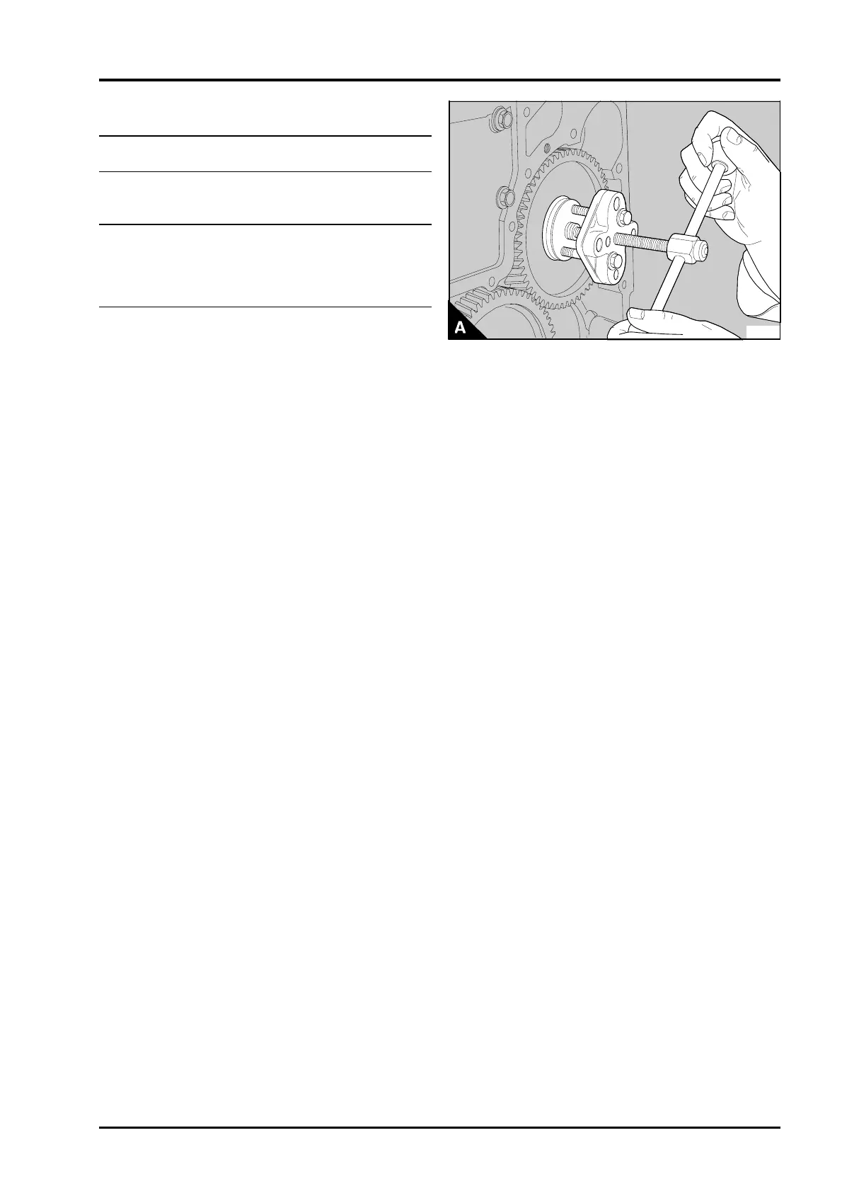
Gear puller, PD.155C
Adaptors for use with PD.155C, PD.155B-5
1Remove the fan, operation 21A-04.
2Remove the drive belts, operation 23A-03.
3Remove the crankshaft pulley, operation 14A-01.
4 If necessary, remove the fan drive pulley,
operation 21A-05.
5 For gear driven coolant pumps: Drain the coolant
and remove the coolant pump, operation 21A-02.
Note: It is not necessary to remove the coolant
pump, when the pump is belt driven.
6Remove the timing case cover, operation
15A-01.
Caution: For fuel injection pumps fitted with a
locking screw. Check that the shaft of the fuel
injection pump is not locked, see operations
20D-06B for Bosch pumps or 20D-06 for Lucus
DP 200 pumps.
7 Rotate the crankshaft until the marked teeth of
the crankshaft gear, the camshaft gear and the fuel
pump gear are all in mesh with the idler gear. The
marked teeth of the idler gear will not necessarily
be in mesh with the marked teeth of the other
gears because of the different speed of rotation of
the idler gear.
8 Remove the nut and the spring washer from the
fuel pump gear.
Notes:
• Early Phaser 210 Ti engines have a spacer
between the gear and the spring washer.
• On certain engine types where the gear is
retained by a plate and four cap screws, release the
four cap screws and remove the plate and then the
gear. Ensure that the plate does not fall when the
cap screws are removed.
9Remove the idler gear, operation 15A-03.
10 Remove the fuel pump gear with the puller and
the adaptors (A). Ensure that the key in the fuel
pump shaft is not lost.
11 Inspect the gear for wear and other damage
and renew it, if necessary.
PA133
Perkins Phaser/1000 Series, April 1995 15A.11