12 CYLINDER HEAD ASSEMBLY
Valves and valve springs
To remove and to fit12A-08
Special tools:
Valve spring compressor, PD.6118B
Stud adaptor, PD.6118-7
Setscrew adaptor, PD.6118-8
To remove
1Remove the cylinder head, operation 12A-07.
2 Clean the bottom face of the cylinder head and
check the depth of the heads of the valves below
the face of the cylinder head, see operation 12A-09.
3 Make a suitable mark on the heads of the valves
to ensure that the valves can be fitted in their
original positions, if they are to be used again.
Warning! Wear eye protection during this operation.
Caution: Ensure that the valve springs are
compressed squarely or the valve stem can be
damaged.
4 Use the valve spring compressor and the
relevant adaptor to compress the valve spring(s)
and remove the collets.
5 Release the valve spring compressor and
remove the valve spring cap, valve spring(s), valve
stem seal and the valve seat washer.
6 Repeat items 4 and 5 for the other valves.
To fit
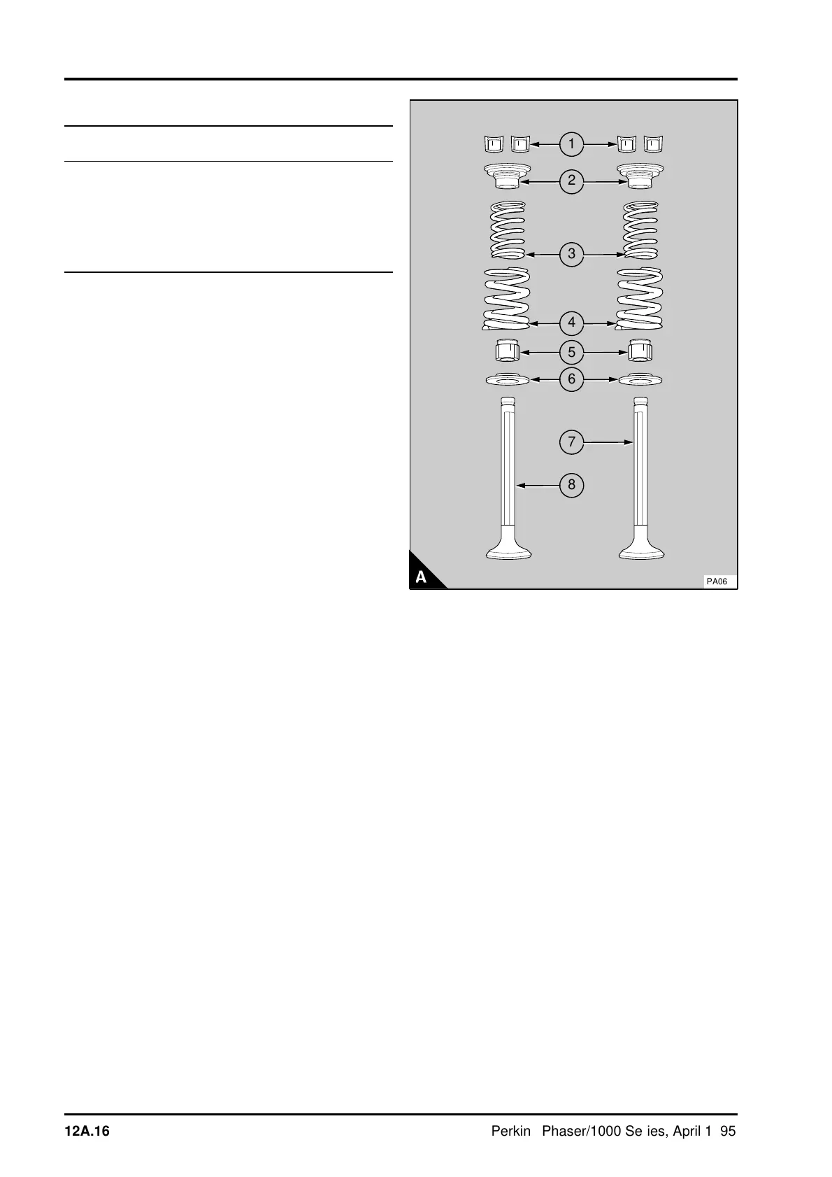
Note: The components of the valve assembly are
shown in A. Certain engines are fitted with single
valve springs.
1 Lubricate the valve stems (A7 and A8) with clean
engine oil and fit the valves in their respective
guides.
2 Fit the spring seat washers (A6). Fit new valve
stem seals (A5) on the valve guides. If double valve
springs are used, fit the inner and outer valve
springs (A3 and A4) on the spring seat washers
with their damper coils toward the cylinder head. If
single valve springs are used, the spring does not
have a damper coil and it can be fitted with either
end to the cylinder head. Fit the valve spring caps
(A2).
Warning! Wear eye protection during this operation.
Caution: Ensure that the valve springs are
compressed squarely or damage can occur to the
valve stem
.
3 Use the valve spring compressor and the
relevant adaptor to compress the valve spring(s)
and fit the collets (A1).
a
a
1
a
a
2
a
a
a
4
a
a
3
a
a
5
a
a
6
a
a
7
a
a
8
PA062
12A.16 Perkins Phaser/1000 Series, April 1995