LUBRICATION SYSTEM 19
Flexible oil pipes
The latest oil cooler pipes fitted to 6 cylinder
Phaser and 1000 Series engines do not have metal
braid and are separate pipes. The part number of
the pipes is stamped on a clip which is fastened to
one end of each pipe. The pipes are not
interchangeable and it is important that the correct
pipes are fitted to the engine.
To remove, to fit and to inspect19A-11
There are two arrangements (A) or (B) for the pipes
which are used in accordance with the application:
To remove
Warning! The engine oil may be hot, allow the
engine temperature to cool down before the oil
pipes are released.
1 Allow the engine temperature to cool down and
put a suitable drip tray under the filter head.
2 Remove the three setscrews which retain the oil
pipes to the filter head. Release the oil pipes and
allow the oil to drain into the drip tray. Discard the
joint.
3 Remove the three setscrews which retain the oil
pipes to the oil cooler. Discard the joint.
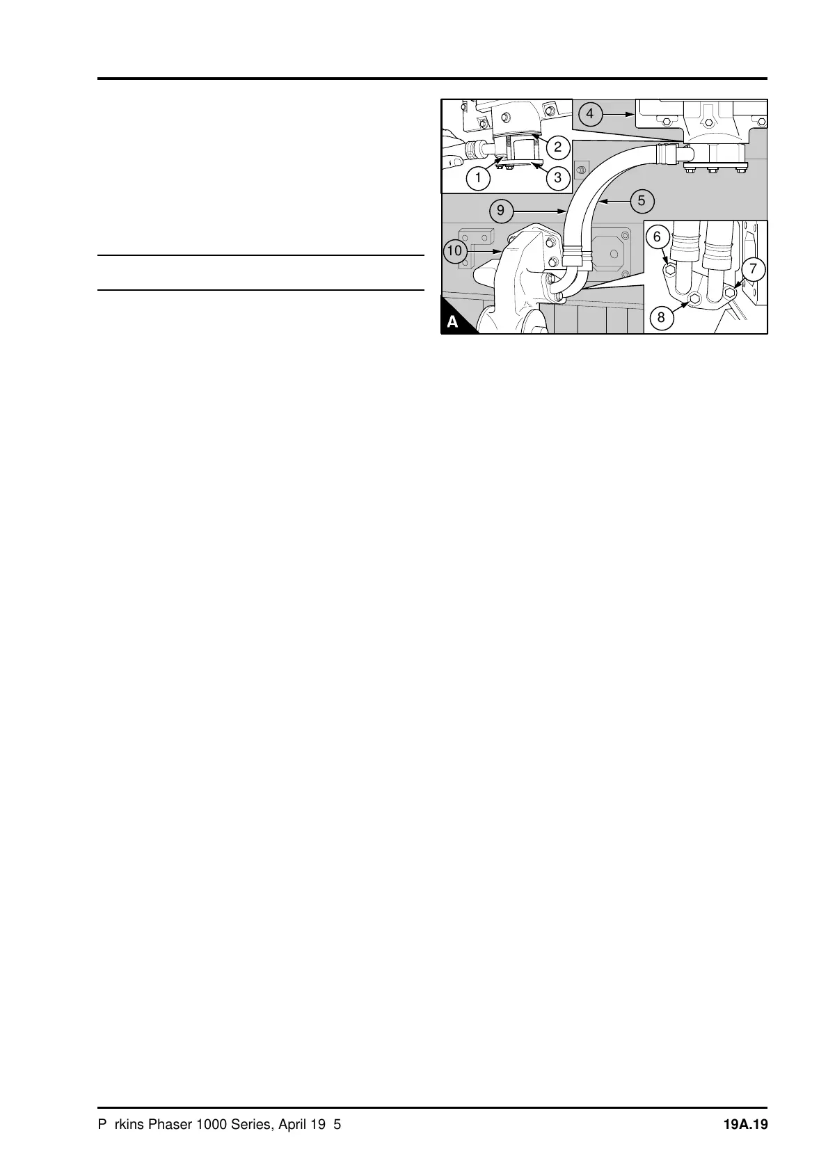
To fit the pipes - arrangement 1:
1 Put the three setscrews into position in the
flange (A3) of the inner pipe (A5), part number
2483A005. Put a new joint (A2) in position on the
setscrews.
2 Engage the setscrews by three or four threads in
the flange of the oil cooler (A4). Engage the spigot
(A1) of the outer pipe (A9), part number 2483A006,
in the hole in the flange (A3) of the first pipe,
ensure that it fits squarely in the flange.
3 Support the pipes by hand and tighten the centre
setscrew finger tight. Tighten the other setscrews
until they are finger tight. Ensure that the pipes are
as close together as possible, then tighten the
setscrews gradually and evenly to 22 Nm (16 lbf ft)
2,2 kgf m.
4 Put a setscrew (A7) in position in the flange of
the inner pipe (A5) for the oil filter head (A10). Put
a new joint in position on the setscrew. Hold the
flange and the joint in position and fit the centre
setscrew (A8). Tighten the setscrews finger tight.
Put the flange of the outer pipe (A9) in position and
fit the third setscrew (A6), tighten it finger tight.
Beginning with the centre setscrew, tighten the
three setscrews to 22 Nm (16 lbf ft) 2,2 kgf m.
PA304
a
a
1
a
a
3
a
a
2
5
6
8
a
a
4
a
a
9
a
a
a
a
10
7
Perkins Phaser/1000 Series, April 1995 19A.19