CYLINDER HEAD ASSEMBLY 12
To inspect and to correct12A-09
Special tool:
Gauge, valve depth, PD.41D
Dial gauge for use with PD.41D, PD.208
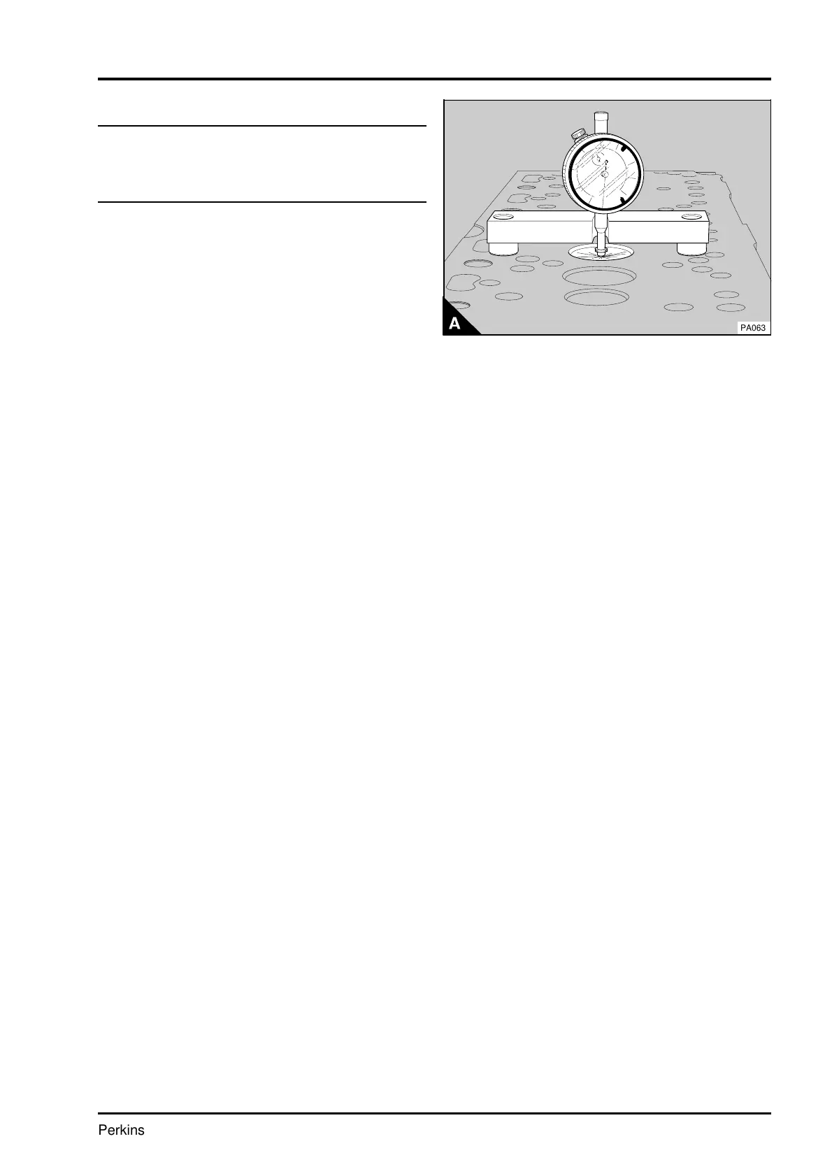
1 Check the depth of the valves below the face of
the cylinder head before the valve springs are
removed.
2 Ensure that the heads of the valves and the
bottom face of the cylinder head are clean.
3 Put the valve depth gauge on the face of the
cylinder head and zero the dial gauge.
4 Carefully put the valve depth gauge in position
over the head of each valve (A) and make a note of
the measurement. The maximum depth, in service,
is given in the data and dimensions.
5 If a valve is below the depth limit, check the
valve depth with a new valve in position. If the valve
depth is still below the limit and a valve seat insert
is fitted, the insert must be renewed.
6 Where a valve seat insert is not fitted, the bottom
face of the cylinder head can be machined to
reduce the valve depth, or an insert can be fitted,
operation 12A-14.
Caution: If the bottom face of the cylinder head is
to be machined, ensure that the thickness, of the
cylinder head will not be less than 102,48 mm
(4.035 in) after the cylinder head has been
machined.
7 Check the valves for cracks. Check the stems of
the valves for wear and for correct fit in their valve
guides.
8 Check that the seat faces of the valves are not
badly burnt or damaged. Seat faces of valves which
are damaged can be ground on a special machine.
Valves which have only a little damage can be
lapped to their valve seats. When new valves are
fitted, the valve depths must be checked, see
paragraph 1.
9 Check that the load on the valve springs is
correct at their fitted length, see the data and
dimensions. Fit new valve springs at every
complete engine overhaul.
PA063
Perkins Phaser/1000 Series, April 1995 12A.17