12 CYLINDER HEAD ASSEMBLY
Valve guides
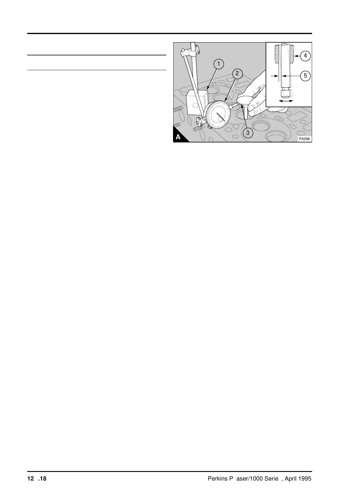
To inspect12A-10
To check the valve guides for wear: The maximum
clearance (A5), between the valve stem and the
bore of the guide is 0,13 mm (0.005 in) for inlet
valves and 0,15 mm (0.006 in) for exhaust valves. If
the clearance, with a new valve fitted, is more than
the limit, then a new valve guide (A4) must be
fitted.
It is recommended that the procedure given below
is used to check the valve guide clearance:
1 Put a new valve in the valve guide.
2 Put a dial test indicator with a magnetic base
(A1) onto the face of the cylinder head
3 With the valve lifted 15,0 mm (0.6 in) and the
gauge (A2) in contact with the edge of the valve
head (A3), move the valve radially away from the
gauge. With the valve held in this position, set the
gauge zero.
4 Move the valve radially across the axis of the
cylinder head towards the gauge. Make a note of
the reading on the gauge. If the reading is equal to
or greater than the data given below, a new valve
guide (A4) must be fitted.
Maximum permissible clearance with a valve lift of
15,0 mm (0.6 in) :
• Inlet guide 0,24 mm (0.009 in)
• Exhaust guide 0,32 mm (0.013)
a
a
5
a
a
4
a
a
a
1
a
a
2
PA298
3
12A.18 Perkins Phaser/1000 Series, April 1995