CRANKSHAFT ASSEMBLY 14
To dismantle and to assemble14A-11
Consumable products:
POWERPART Nutlock
To dismantle
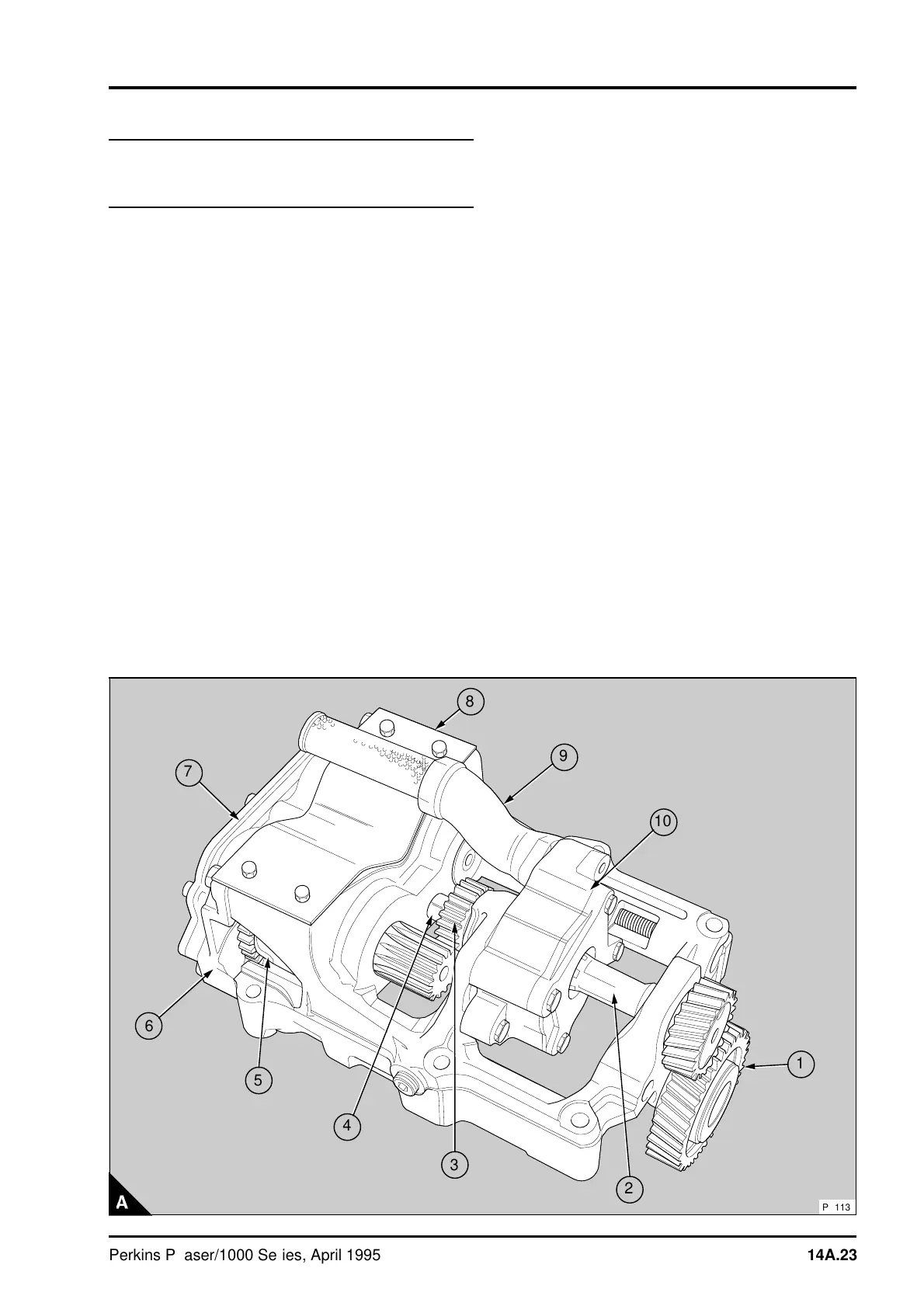
1 Remove the balance weight cover (A8).
2 Release the setscrew and remove the idler gear
assembly (A1). Keep the components together as
an assembly to protect the needle roller bearing.
3 Prevent movement of the drive shaft (A2) and
loosen the nut (A4) of the drive gear for the balance
weights (A3). Put a suitable flat distance piece in
position between the nut and the balancer frame.
Turn the nut until it is against the face of the
distance piece. Continue to turn the nut with a
suitable spanner until the Loctite seal on the splines
of the drive shaft is broken and the gear is loose on
the shaft. Remove the nut and the drive gear and
remove the drive shaft. Ensure that the needle
roller bearings are not damaged when the drive
shaft is removed.
4 Release the setscrews which hold the lubricating
oil pump and the suction pipe (A10 and A9) to the
balancer frame and remove the lubricating oil pump
and the suction pipe.
5 Release the setscrews and remove the transfer
plate and joint for the lubricating oil (A7) from the
rear of the balancer unit. Make a note of the
position of the direction arrows on the outside of
the transfer plate (14A.26/B or C) to ensure that it
can be assembled correctly .
a
a
2
a
a
3
a
a
5
6
a
a
7
8
9
a
a
a
a
10
a
a
1
a
a
4
PA113
Perkins Phaser/1000 Series, April 1995 14A.23