14 CRANKSHAFT ASSEMBLY
Balancer unit
To remove and to fit14A-10
To remove
1 Drain the lubricating oil from the sump and
remove the sump, operation 19A-03.
Warning! The weight of the unit is approximately
25 kg (55 lb).
2 Provide a support for the balancer unit before
release of the setscrews from the engine.
3 Release the setscrews and lower carefully the
balancer unit. Make a note of the positions of the
setscrews of different lengths.
To fit
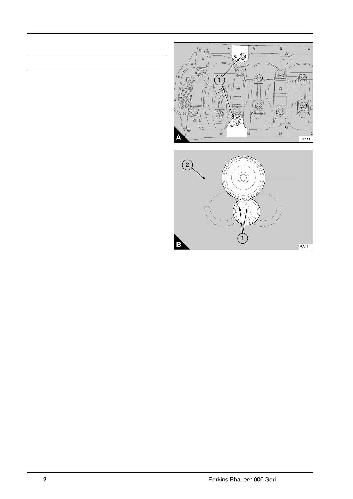
1 Ensure that the contact faces of the cylinder
block and of the balancer unit are clean and that
the two thimbles (A1) are fitted correctly to the
cylinder block.
2 Set the piston of number 1 cylinder to TDC,
operation 17A-01.
3 Before the balancer unit is fitted, ensure that the
flat faces of the balance weights are level with each
other (B1) and the weights hang down away from
the cylinder block (B2). The timing of the balance
weights to the drive shaft is correct when the large
hole and small hole in the front of the drive shaft
gear are in the positions shown in the illustration
(B).
Note: If the gear position shown in (B) cannot be
obtained, then the balancer must be partially
dismantled and the timing corrected (14A.26/A).
4 Fit the balancer unit to the cylinder block with the
correct screws in the centre positions of the
balancer frame. Ensure, when the idler and
crankshaft gears are in mesh, that the flat faces of
the balance weight are level with each other and
that they are towards the cylinder block. Check that
the balancer unit is fitted correctly on the thimbles
and fit the remainder of the setscrews in their
correct position. Tighten the setscrews to 54 Nm
(40 lbf ft) 5,5 kgf m.
5 Rotate the crankshaft through two turns to
ensure that it is free to rotate.
6Fit the lubricating oil sump, operation 19A-03 and
fill the sump to the correct level with an approved
oil.
a
a
1
PA111
a
a
1
a
a
2
PA112
14A.22 Perkins Phaser/1000 Series, April 1995