CYLINDER HEAD ASSEMBLY 12
Valve tip clearances
To check and to adjust12A-05
Notes:
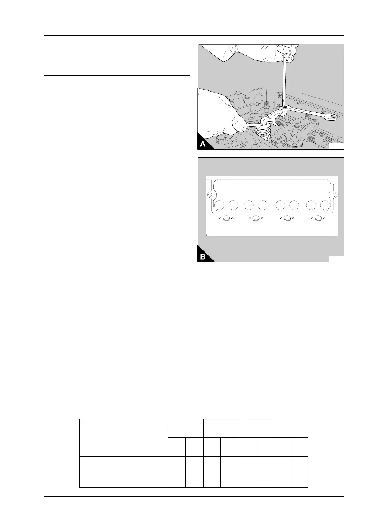
• The valve tip clearance is measured between the
top of the valve stem and the rocker lever (A). With
the engine hot or cold, the correct clearances are
0,20 mm (0.008 in) for the inlet valves and
0,45 mm (0.018 in) for the exhaust valves. The
valve positions are shown at (B).
• The sequence of valves from number 1 cylinder
is shown in the table below. Number 1 cylinder is at
the front of the engine.
Four cylinder engines
1 Rotate the crankshaft in the normal direction of
rotation until the inlet valve (B8) of number 4
cylinder has just opened and the exhaust valve (B7)
of the same cylinder has not closed completely.
Check the clearances of the valves (B1 and B2) of
number 1 cylinder and adjust them, if necessary.
2 Set the valves (B3 and B4) of number 2 cylinder
as indicated above for number 4 cylinder. Then
check / adjust the clearances of the valves (B5 and
B6) of number 3 cylinder.
3 Set the valves (B1 and B2) of number 1 cylinder.
Then check / adjust the clearances of the valves
(B7 and B8) of number 4 cylinder.
4 Set the valves (B5 and B6) of number 3 cylinder.
Then check / adjust the clearances of the valves
(B3 and B4) of number 2 cylinder.
PA049
1 2 3 4 5 6 7 8
PA050
Cylinder
and
Valve number
1
12
2
34
3
56
4
78
Valve
I = Inlet
E = Exhaust
IEEI IEEI
Perkins Phaser/1000 Series, April 1995 12A.07