12 CYLINDER HEAD ASSEMBLY
Six cylinder engines
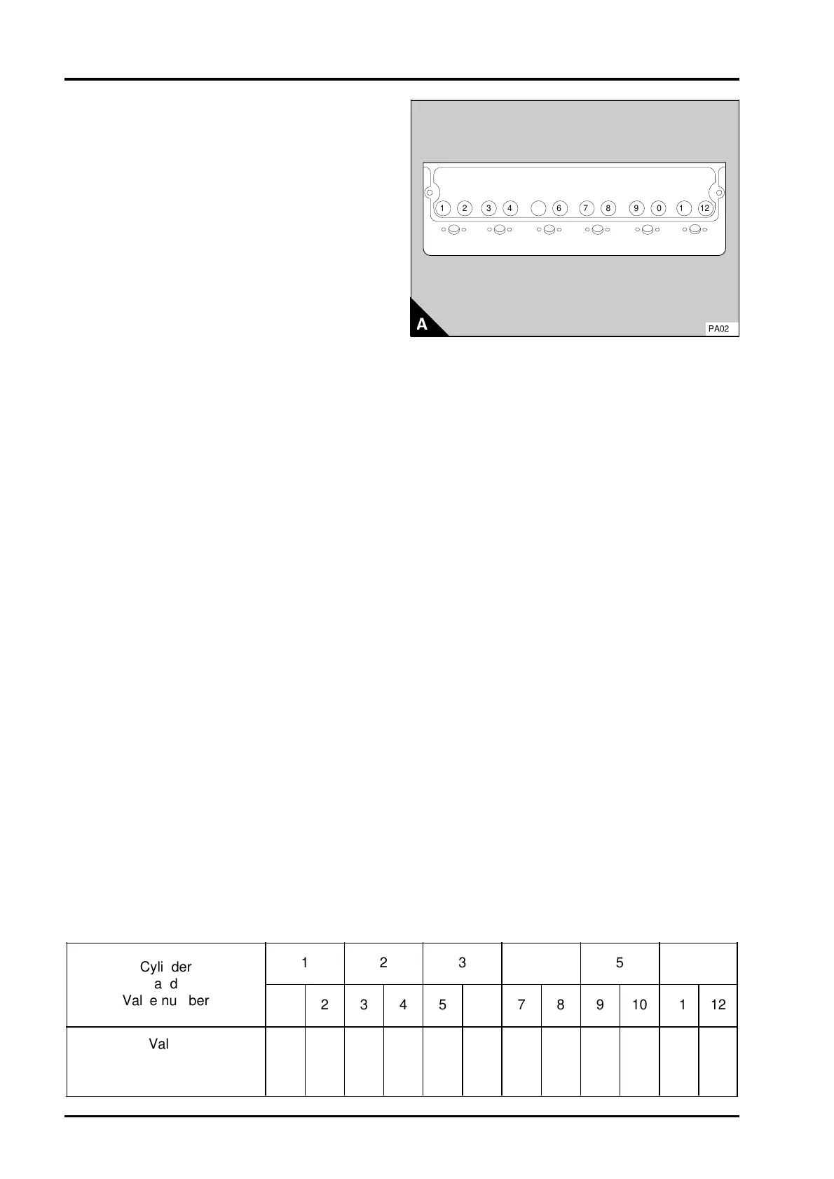
1 Rotate the crankshaft in the normal direction of
rotation until the inlet valve (A12) of number 6
cylinder has just opened and the exhaust valve
(A11) of the same cylinder has not closed
completely. Check the clearances of the valves
(A1 and A2) of number 1 cylinder and adjust them,
if necessary.
2 Set the valves (A4 and A3) of number 2 cylinder
as indicated above for number 6 cylinder. Then
check / adjust the clearances of the valves
(A9 and A10) of number 5 cylinder.
3 Set the valves (A8 and A7) of number 4 cylinder.
Then check / adjust the clearances of the valves
(A5 and A6) of number 3 cylinder.
4 Set the valves (A1 and A2) of number 1 cylinder.
Then check / adjust the clearances of the valves
(A11 and A12) of number 6 cylinder.
5 Set the valves (A9 and A10) of number 5
cylinder. Then check / adjust the clearances of the
valves (A3 and A4) of number 2 cylinder.
6 Set the valves (A5 and A6) of number 3 cylinder.
Then check / adjust the clearances of the valves
(A7 and A8) of number 4 cylinder.
1
4
2
3
5
6
7
8
9
10
12
11
PA028
Cylinder
and
Valve number
1
12
2
34
3
56
4
78
5
910
6
11 12
Valve
I = Inlet
E = Exhaust
IEEI IEEI IEEI
12A.08 Perkins Phaser/1000 Series, April 1995