16 CYLINDER BLOCK ASSEMBLY
To remove and to fit16A-05
Special tools:
Remover/replacer for cylinder liner (main tool),
PD.150B
Adaptors for use with PD.150B, PD.150B-17
Depth gauge, liner flange, PD.41D
Dial gauge for use with PD.41D, PD.208
Consumable products: (See Section 10)
POWERPART Retainer (oil tolerant)
Loctite Safety Solvent or a similar product
Where several liners are to be removed or a very
tight production liner is fitted, a press should be
used. Where a single liner is to be removed or the
crankshaft is to remain in position, a tool for hand
operation is available.
To remove
1 Drain the lubricating oil and remove the
lubricating oil sump, operation 19A-03.
2Remove the cylinder head assembly, operation
12A-07.
3 Remove the piston and connecting rod
assembly, see operation 13A-03.
4 Carefully remove the piston cooling jet, where
fitted, operation 13A-09.
5 Rotate the crankshaft to give access to the
cylinder liner. Protect the crank pin.
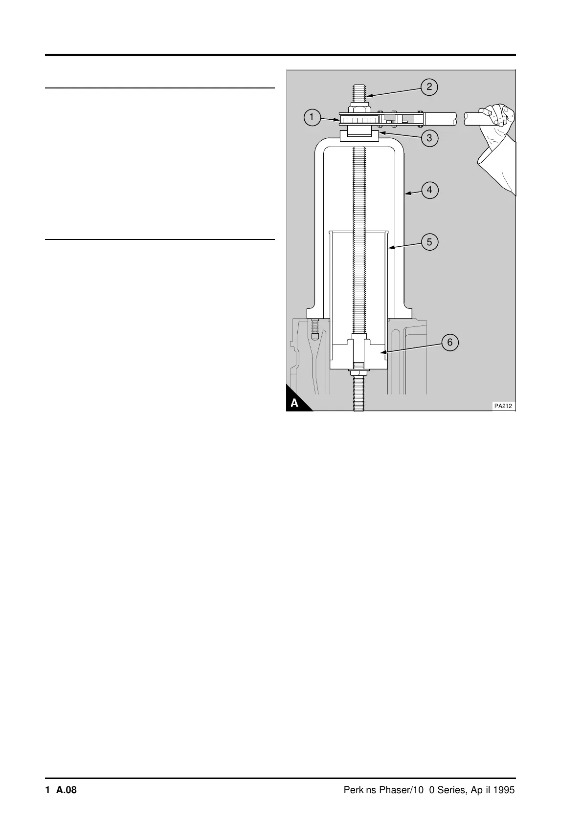
6 Put the tool (A4) on the top face of the cylinder
block and over the centre of the liner (A5). Ensure
that the base of the tool is not on top of the liner
flange of the next cylinder.
7 Put the bearing (A3) in the recess in the top of
the tool with the flat face of the bearing to the
bottom of the recess.
8 Fit the threaded rod (A2) through the bearing and
the top of the tool until the handle (A1) is in the
recess in the top of the bearing. In this position
adjust the threaded rod until the end is below the
bottom of the cylinder liner. Fit the adaptor
PD.150B-17/1 (A6) onto the threaded rod and
against the bottom of the cylinder liner. Ensure that
the two lugs on the top of the adaptor engage with
the flats on the threaded rod. Fit the washer and
nut and tighten the nut onto the adaptor.
9 Lubricate the ratchet of the handle and the
threaded rod with Shell Spirax oil or an equivalent
oil. Operate the handle and pull the cylinder liner
out of the top of the cylinder block.
a
a
2
1
a
a
3
a
a
4
a
a
5
6
PA212
16A.08 Perkins Phaser/1000 Series, April 1995