19 LUBRICATION SYSTEM
Lubricating oil pump
To remove and to fit19A-06
For four cylinder engines fitted with a balancer unit ,
the oil pump is integral with the balancer unit, see
section 14 for removal instructions.
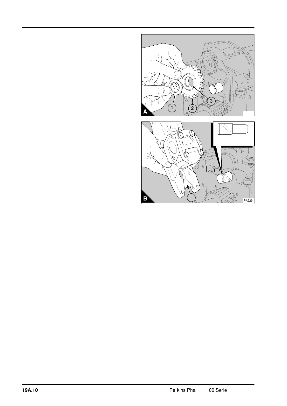
The latest engines have a new lubricating oil pump
which has a channel (B1) in the body of the pump.
Lubricating oil from the front main bearing passes
down the channel in the body of the pump to an oil
hole in the idler shaft. The lubricating oil then
passes through the hole in the idler shaft to the
bush in the idler gear.
To remove
1 Drain the lubricating oil and remove the
lubricating oil sump, operation 19A-03.
2Remove the suction pipe and strainer, operation
19A-04.
3 For four cylinder engines: Remove the oil
pressure relief valve, operation 19A-08, and the
delivery pipe. For six cylinder engines: Remove the
delivery pipe of the oil pump.
4 The oil pump is fitted to number 1 main bearing
cap. The oil pump can be removed with the main
bearing cap, if a suitable spanner is available that
will enable the torque to be applied correctly to the
setscrews of the main bearing cap when it is fitted.
If a suitable spanner is not available, the timing
case must be removed, operation 15A-08.
5 Release the circlip which retains the idler gear of
the oil pump and remove the washer (A1) and the
idler gear (A2).
6 Release the setscrews and remove the oil pump
(B).
PA228
3
2
1
PA229
1
19A.10 Perkins Phaser/1000 Series, April 1995