PISTON AND CONNECTING ROD ASSEMBLIES 13
Connecting rod
To inspect13A-07
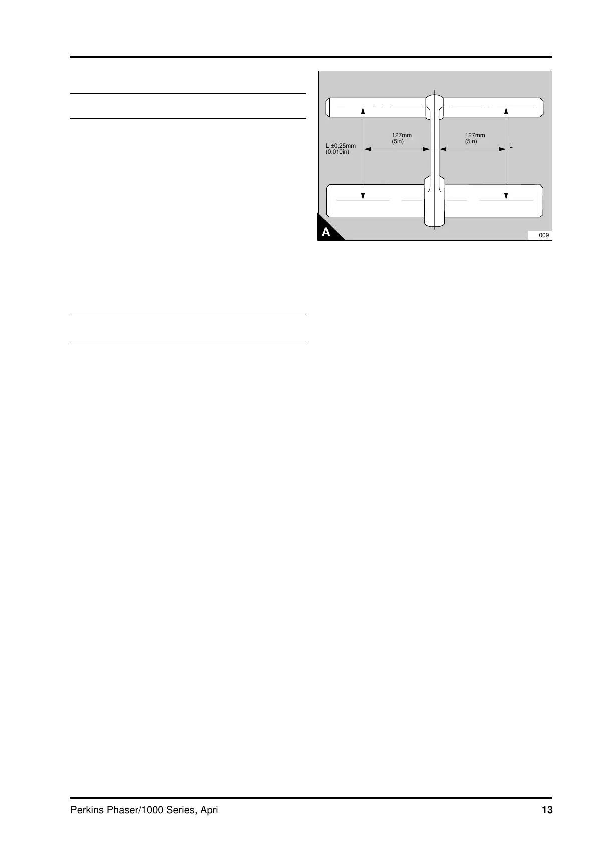
1 Check the connecting rod for distortion (A).
Note: The large and small end bores must be
square and parallel with each other within the limits
of +/- 0,25 mm (0.010 in) measured 127 mm
(5.0 in) each side of the connecting rod axis on a
test mandrel. With the small end bush fitted, the
limits are reduced to +/- 0,06 mm (0.0025 in).
2 Check the small end bush for wear or for other
damage and renew it, if necessary.
3 Check the fit of the gudgeon pin in the small end
bush and check the gudgeon pin for wear, see the
data and dimensions.
Small end bush
To remove and to fit13A-08
1 Press out the old bush with a suitable adaptor.
2 Clean the connecting rod bore and remove any
sharp edges.
3 Press in the new bush. Ensure that the
lubrication hole in the bush is on the same side as,
and is aligned with, the hole in the top of the
connecting rod.
4 Ream the bush to get the correct clearance
between the gudgeon pin and the bush, see the
data and dimensions.
Note: On turbocharged engines the small end is
wedge shaped. After the small end bush has been
fitted, machine the bush to the shape of the small
end and remove any sharp edges.
a
a
a
a
a
a
a
a
a
a
a
a
a
a
a
a
L ±0,25mm
(0.010in)
a
a
a
a
a
a
a
a
a
a
a
a
a
a
a
127mm
(5in)
a
a
a
a
a
a
a
a
a
a
a
a
a
a
a
127mm
(5in)
a
a
a
a
a
a
a
a
a
a
a
a
a
a
a
a
L ±0,25mm
(0.010in)
PG009
Perkins Phaser/1000 Series, April 1995 13A.13