ASPIRATION SYSTEM 18
To remove and to fit the actuator
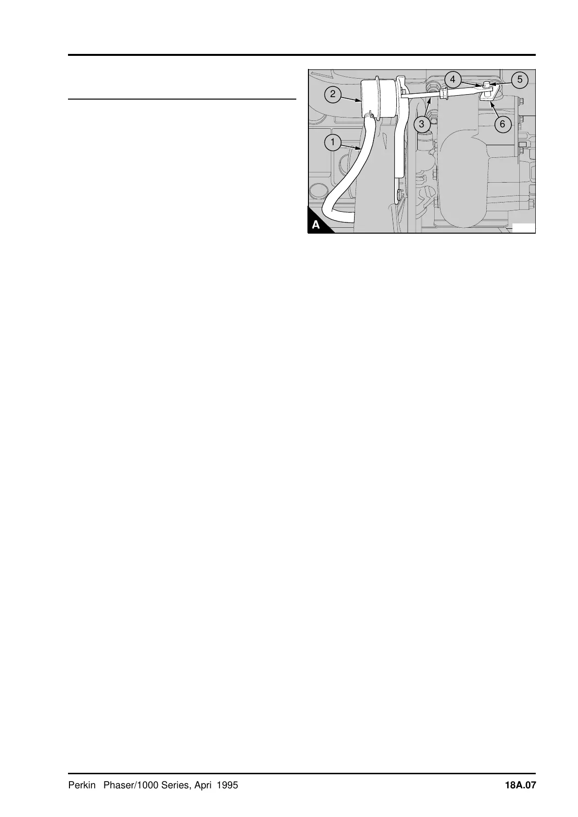
assembly of the waste-gate unit18A-03
It is important that the waste-gate actuator setting is
not altered. Do not remove the actuator or
mounting bracket unless it is necessary to renew
the actuator assembly.
If a waste-gate actuator or mounting bracket
assembly is removed from a turbine or compressor
housing it is important that the bracket is fitted into
the correct position on the housing.
To remove
1 Disconnect the boost sensor pipe (A1) at the
actuator (A2).
2 Remove the clip (A4) which retains the actuator
rod (A3) and lift the end of the actuator rod off the
pin (A5) of the waste-gate valve.
3 Release the setscrews which retain the actuator
bracket to the turbocharger and remove the
actuator and bracket assembly.
To fit
1 Put the actuator and bracket assembly in position
on the turbocharger and tighten the setscrews.
2 Connect to the actuator (A2) an air supply which
can be adjusted accurately and is fitted with an
accurate gauge.
3 Operate the arm (A6) of the waste-gate valve by
hand to check that the valve is free to move.
4 Push the arm of the waste-gate valve as far as
possible toward the actuator and hold the arm in
this position. Slowly apply air pressure to the
actuator until the end of the actuator rod (A3) will fit
easily onto the pin (A5) of the waste-gate valve. Fit
the clip (A4). Release the air pressure.
Caution: Do not apply an air pressure of more than
205 kPa (30 lbf/in
2
) 2,1 kgf/cm
2
to the actuator.
Higher pressures may damage the actuator.
5 Check the operation of the waste-gate unit,
operation 18A-04.
PA184
a
a
4
a
a
5
a
a
2
a
a
a
1
a
a
6
3
Perkins Phaser/1000 Series, April 1995 18A.07