20A FUEL SYSTEM
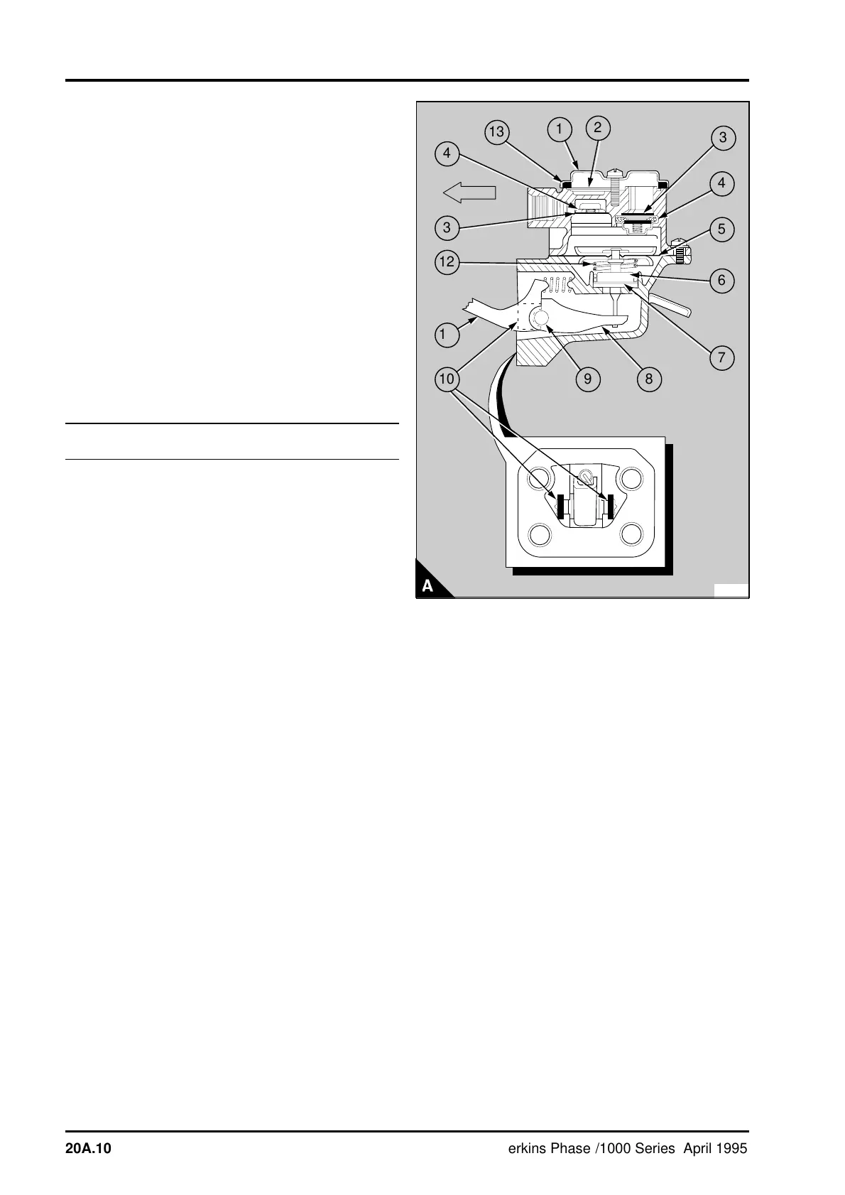
5 Put the diaphragm assembly in position over the
lower half of the body with the blade of the pull rod
aligned with the slot in the link arm. Press lightly
down on the diaphragm until the notch in the pull
rod is in the slot in the link arm and turn the
diaphragm 90° in either direction. This action will
engage and retain the pull rod in the slot of the link
arm.
6 Push the rocker arm towards the pump body
until the diaphragm is level with the body flange and
fit the top half of the body in position with the marks
on the flanges aligned. Keep the pressure on the
rocker arm; fit the spring washers and the screws
and tighten them evenly.
7 Fit the gauze filter (A2) and the cover (A1),
ensure that the rubber seal (A13) is fitted correctly
and tighten the screw.
To test20A-05
1 Disconnect the fuel outlet pipe from the fuel lift
pump. Fit a 0-70 kPa (0-10 lbf/in
2
) 0-0,7 kgf/cm
2
pressure gauge to the outlet of the lift pump.
Release the connection at the gauge and operate
the priming lever of the lift pump to eliminate air
from the pipe. When fuel, free of air, flows from the
pipe tighten the connection. Ensure that there are
no leaks at the connections between the pump and
the gauge.
2 Operate the starter motor for 10 seconds with
the engine stop control in the stop position or with
the stop solenoid disconnected.
3 Note the maximum pressure indicated on the
gauge. If the pressure indicated is less than the test
pressure shown in the data and dimensions, repair
or renew the pump. Also check the rate at which
the pressure reduces to half the maximum pressure
obtained. If this is less than 30 seconds, repair or
renew the pump.
4 Remove the gauge and connect the outlet pipe
to the lift pump. Release the vent screw on the fuel
filter head and operate the priming lever until fuel,
free of air, flows from the vent screw. Tighten the
vent screw.
5 Connect the engine stop solenoid.
PA252
a
a
1
a
a
2
a
a
3
a
a
4
a
a
a
5
a
a
6
a
a
7
8
9
a
a
a
a
10
a
a
a
a
11
a
a
a
a
a
a
12
3
4
a
a
a
a
13
20A.10 Perkins Phaser/1000 Series, April 1995