FUEL SYSTEM 20A
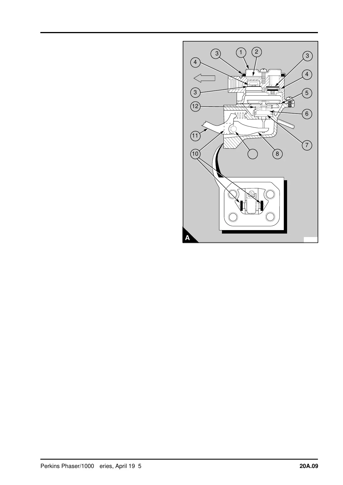
3 Remove the cover (A1) and the gauze (A2).
Release the setscrews and separate the two halves
of the pump.
4 Turn the diaphragm assembly (A5) 90° to
release the pull rod from the link arm (A8) and
remove the diaphragm assembly. Remove the stem
seal (A6), the spring seat washer (A7) and the
spring (A12) from the pull rod. The diaphragm and
pull rod assembly is renewed as an assembly and
no service is possible on the diaphragm.
5 The valves (A4) are peened in and can be
removed with a suitable lever. Some of the peened
metal will have to be removed before the valves
can be removed.
6 To remove the link arm: Hold the rocker lever
(A11) in a vice and hit the body of the lift pump with
a soft face hammer to release the two retainers
(A10). Be careful not to damage the joint face of
the pump body. Remove the rocker lever, the pin
(A9), the link arm and the return spring. Check the
components for wear and other damage.
To assemble
1 Thoroughly clean the valve housings. Fit new
seat washers (A3) and push the new valves (A4)
into position. As the valves are the same, but one
valve is fitted in reverse of the other, it is possible
to fit the valves upside down. To ensure that the
valves are fitted correctly, fit them as shown in A.
When the valves are correctly fitted, peen the edge
of the valve housings in six places, evenly divided,
to keep the valves in position.
2 Fit the rocker lever (A11), pin (A9) and link arm
assembly (A8) into the bottom half of the lift pump.
Fit the return spring; ensure that the ends of the
spring are in their correct location.
3 With a light hammer and a suitable adaptor, fit
two new retainers (A10) in their grooves in the
casing until they fasten the pin. Peen the open
ends of the grooves to fasten the retainers in
position.
4 Fit the diaphragm spring (A12) into its location
under the diaphragm (A5) and put the spring seat
washer (A7) and a new stem seal (A6) into position
on the pull rod. Ensure that the small diameter at
the top of the seal is on the round section of the
pull rod.
PA252
1
2
3
a
a
4
a
a
a
5
a
a
6
a
a
7
a
a
8
9
a
a
a
a
10
a
a
a
a
11
a
a
a
a
a
a
12
a
a
3
a
a
a
4
a
a
a
a
a
a
13
Perkins Phaser/1000 Series, April 1995 20A.09