15 TIMING CASE AND DRIVE ASSEMBLY
Idler gear and hub
To remove and to fit15A-03A
To remove
1Remove the fan, operation 21A-04.
2Remove the drive belts, operation 23A-03.
3Remove the crankshaft pulley, operation 14A-01.
4 If necessary, remove the fan drive pulley,
operation 21A-05.
5 Drain the coolant and remove the coolant pump,
operation 21A-02.
6Remove the timing case cover, operation
15A-01.
7 Rotate the crankshaft until the marked teeth of
the crankshaft gear, the camshaft gear and the fuel
pump gear are all in mesh with the idler gear. The
marked teeth of the idler gear will not necessarily
be in mesh with the marked teeth of the other
gears because of the different speed of rotation of
the idler gear.
Note: There are no timing marks on the fuel pump
gear of engines fitted with Bosch in-line fuel
injection pumps. When the idler gear is removed,
the fuel pump gear could move. Before the idler
gear is removed, make a temporary mark on a
tooth of the fuel pump gear to align with a similar
mark on the timing case. It is not necessary to
mark the fuel pump gear if it is to be removed, as
the timing of the fuel pump will be lost.
8 Release the three setscrews, remove the plate of
the idler gear and remove the gear. The drive gear
of the fuel injection pump may rotate counter-
clockwise when the idler gear is removed.
9 Remove the idler gear hub.
Caution: Do not turn the crankshaft with the idler
gear removed.
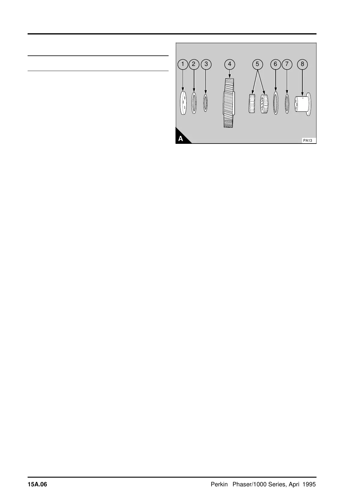
10 For engines that use the idler gear assembly
with needle roller bearings - Release the three
setscrews, remove the plate of the idler gear (A1).
Remove the front thrust washer (A2), the front
spacer (A3) and the gear (A4). Remove the two
needle roller bearings (A5), if these are to be used
again, they should be fitted in their original
positions. Remove the rear thrust washer (A6) and
the rear spacer (A7). Remove the hub (A8).
a
a
7
a
a
6
a
a
5
a
a
8
a
a
4
a
a
3
2
a
a
1
PA132
15A.06 Perkins Phaser/1000 Series, April 1995